Increase speed

Gyro_Kai

Senior Member
Joined
Nov 29, 2006
Messages
3,279
Location
near Frankfurt, Germany
Aircraft
MT-03, Calidus (rent)
Total Flight Time
about 150
Hello,

I was wondering, what could be done, to increase the airspeed of gyros. I understand, that the rotor increases RRPM and produces more lift and therefore more drag when h-speed increases. But if the blades were shaped or hinged in a way, that they produce (a little) less lift, when exceeding a certain speed, wouldn't that make a fast gyro?

Kai.
 
Kai:

Nearly all homebuilt gyros (even most kit gyros that include a pod) are very poorly streamlined. The easiest way to make these gyros go faster is to design a better streamlined fusleage. The simplest way to improve streamlining is to add a fairing over the engine and a spinner on the back face of the prop.

In unaccelerated flight, you must have lift that equals the weight of the gyro.

Coventional gyros must obtain all of this lift from their rotors. An autogyro rotor is a rather inefficient lifting device, however. Small wings can reduce the workload of the rotor and thereby add some airspeed. They tend to cause the rotor to slow down, however. This effect often becomes intolerable somewhere in the 150 mph neighborhood.

A mechanical shaft drive from the engine to the rotor allows the rotor to fly at a lower angle of attack and adds to the gyro's speed range WITHOUT reducing rotor speed. At higher airspeeds, the vertical tail surfaces can provide torque compensation without the need for a tail rotor.
 
If you want a gyro to go faster, then you need to reduce the effects that slow it down the most. That would be the drag from the rotors, and mostly the rearward lift from the 9 degree angle of rotor-disk attack to the forward airflow.

The easiest way is to add some power to the rotor-system. 5 to 10 horsepower will make a substantial improvement.
 
Kai:
Nearly all homebuilt gyros (even most kit gyros that include a pod) are very poorly streamlined. The easiest way to make these gyros go faster is to design a better streamlined fusleage. The simplest way to improve streamlining is to add a fairing over the engine and a spinner on the back face of the prop.
In unaccelerated flight, you must have lift that equals the weight of the gyro.
Coventional gyros must obtain all of this lift from their rotors. An autogyro rotor is a rather inefficient lifting device, however. Small wings can reduce the workload of the rotor and thereby add some airspeed. They tend to cause the rotor to slow down, however. This effect often becomes intolerable somewhere in the 150 mph neighborhood.
A mechanical shaft drive from the engine to the rotor allows the rotor to fly at a lower angle of attack and adds to the gyro's speed range WITHOUT reducing rotor speed. At higher airspeeds, the vertical tail surfaces can provide torque compensation without the need for a tail rotor.

Oops, we were posting at the same time. I didn't mean to be redundant.

But, the problem with a mechanical drive from the engine has problems, because every time you adjust engine power you adjust blade power. A clutch system just burns up power, makes heat and wears out.

With todays light electrical motors, you could apply power to the rotors, and have the means of adjustment, and prerotate! Something to think about.
 
An article published in the PRA magazine several years ago may answer your questions, Kai.

Power
Where does it all go?

The rotor

A rotor, with blade tips running at about 275 mph while the rest of the machine is doing 60 mph or less, isn’t the most efficient way of flying. That’s just for the lightweights; the lead sleds can have blade tips running at 350 mph.

The advantage of a gyroplane is that a rotor never quits flying as long as there is upward airflow through it. A gyro descends vertically at zero airspeed with about the same rate of descent as an equivalent parachute and under full roll/pitch control. The stall of a fixed wing airplane represents a discontinuity; below the stall speed, it abruptly quits flying and falls.

The fuselage

But the rotor is only part of the story. The typical Bensen clone has a horribly draggy airframe and very low propeller efficiency.

Cleanly designed pushers with good airflow to the propeller, typified by the Rutan VariEze type machines, are more efficient than tractors which must fly into their own headwind.

And now, the numbers


The graph was calculated for a 500-lb. GW gyro with a high quality 23-ft. diameter rotor. The open airframe was assumed to have a frontal area of 9 square feet.

Rotor drag has two components; the first being that part of rotor drag chargeable to the production of lift, the downward acceleration of air mass and the second is that part chargeable to moving the rotorblade airfoils through the air, i.e., induced drag and profile drag.

Induced drag is very high at low airspeed because the rotor can’t act on a large mass of air, as the airspeed increases more air mass is presented to the rotor and the acceleration that must be imparted decreases. At an airspeed of 100 mph, induced drag becomes almost negligible.

Rotor profile power in nearly constant, increasing slowly with airspeed. With constant profile power, that portion of rotor drag would decrease with increasing airspeed at a rate of 1/airspeed. Drag is equal to HP x 550/airspeed, fps.

The graph slightly understates rotor profile drag in the upper speed range. As airspeed increases, stall of the retreating blade spreads outward and rotor rpm must increase in order to maintain lift with the reduction of effective blade area. I assumed constant rotor speed to keep the equations as simple as possible.

The rotor disc flies at an angle of attack that is a function of its lift/drag ratio. From the graph, the rotor has a drag of 70 lb. at 50 mph. The drag/lift ratio is 70/500 = .14. This is the tangent of the rotor angle of attack. The resulting angle is 8º. From the graph, the rotor flies at an angle of attack of 15.5º at 30 mph and 4.7º at 80 mph.

Total drag, the sum of rotor and airframe drag is least at 45-50 mph. That would be the airspeed for maximum rate of climb if the propeller was appropriately pitched and also the airspeed for lowest rate of descent with power off.

Comparisons of rotors should be conducted at airspeeds of 45 mph or lower; airframe drag begins masking rotor drag at higher speeds.

Drawbar horsepower is a term usually associated with farm tractors that I included here with some trepidation. If the gyro was towed with a rope attached to scales and the resulting power calculated, the result would be drawbar HP. The total drag at 30 mph is 160 lb. but that only represents a drawbar power of ~13 hp (160 x 30 x1.47/550). The factor 1.47 converts mph to fps and there are 550 ft-lb/sec in one hp.

Propeller efficiency is very low at low airspeed; at zero airspeed, propeller efficiency is also zero, increasing to perhaps 50% at 60 mph and then again decreasing to zero at some high airspeed where it’s a simple screw operating without slippage and not accelerating any air at all.

So there we have it. Gyros will fly at very low airspeed if sufficient thrust is available and would be better at high airspeed than most people realize with a truly streamlined fuselage but never equaling the performance of their FW counterparts.
 

Attachments

  • Increase speed
    drag.jpg
    38.5 KB · Views: 0
Magnificient, thanks. Still the graph stops at 100mph and doesn't promise to get better when speed is increased. So additonal fixed wings seems to be the only solution? Tilting the rotor forward seems not a good choice without additional wings to fly (Carter has both).


Kai.
 
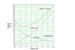
I had arbitrarily stopped the graph at 100 mph, Kai, because the drag of an open airframe gyro becomes prohibitively high.

But of course we can streamline the fuselage and install more power. The ultimate limit of top speed is the rotor itself; that limit being compressibility effects of the advancing rotor blade tips.

Cierva knew most of the answers ~75 years ago. The following is an OCR of a paper written by Cierva in 1934.


High Speed Autogiros


Continuing the policy which this company has followed in its technical development, it appears that now that all the secondary problems of the direct-control system seem to be satisfactorily solved, the time is ripe to take a definite step in one of the directions more promising for the utilization of the peculiar high speed-range qualities of the Autogiro.

If a machine with a top speed of the order of 200 mph could be produced that retains
substantially the slow flying characteristics of our existing machines, there is no question
that such a machine will have tremendous practical possibilities.

There are two problems present in the design of a high speed-range Autogiro. One is the cleaning up of the design so as to reduce the possible drag to a minimum figure which should be comparable to that of an equivalent high-speed airplane. The other is to design a rotor having a minimum solidity, allowing in consequence a large rotor disc area in compar-ison with the actual blade area.

The latest Autogiro, the C.30P, has a rotor whose solidity is unnecessarily small for the top speed of the machine, since the tip speed to forward speed ratio at top speed is between 2.5 and 3, while previous experiments have illustrated the fact that it could be as low as 1.7 or so, with advantage from the efficiency point of view and without appreciable vibration being developed.

This means that if the C.30 were clean enough or had power enough to have a top speed of the order of 160 mph, its rotor should be satisfactory without modification, assum-ing the weight of the machine unchanged, its low-speed characteristics should be approxi-mately equivalent to the present.

The solidity of the C.30 rotor is approximately 0.047 and while extremely low it can-not be considered by any means as the lowest possible in practice. By building the blades in the metal type of construction which this Company, in conjunction with Messrs. G. and J. Weir, is developing at present, it is considered as perfectly feasible lowering solidity by some 20 percent if necessary. As the top speed depends on the loading per square foot of blade area while the slow-speed characteristics depend almost exclusively on the loading per square foot of disc area, it is easy to reach the conclusion that top speeds of the order of 200 mph could be obtained with rotors of solidities of some 0.038 and disc loadings of 2 to 2.1 lb/sq ft (9.7—10.2 kg/sq m) which is not more than the disc loading of some Autogiros which have proved very satisfactory on their slow speed characteristics. As the loading of C.30 is approximately 1.7 lb/sq ft (8.3 kg/sq m), it means that a loading of 2.1 lb/sq ft (10.2 kg/sq m) means an increase of only about 10 percent in the minimum horizontal speed, in the vertical speed of descent, and in the landing.

In order to increase somewhat the tip speed for a given blade loading it would be possi-ble to decrease either the chord of the blade toward the tip or the thickness of the section, or both. Decrease of the chord will probably not contribute anything toward increased effI-ciency at high speed, but decrease in the relative thickness of the section probably would, considering in particular the very high relative air speeds which will be attained by the tip of the blade which advances, and so it is proposed to give the blades of the high speed-range machines taper in thickness toward the tip.

In order to obtain the lowest possible figure for a parasite drag, it will be advisable to use air-cooled inline or H engines, to retract the undercarriage during flight into the fuse-lage, to use a single-strut pylon of minimum section inside of which will be contained the mechanical transmission for the rotor starter and all the rotor controls, to design rotor hub and articulations with a minimum of frontal area, and to build cantilever tails with perfect streamlined attachments to the fuselage.
In view of the preceding considerations, the following preliminary specifications for
two machines designated as C.31 and C.32 respectively are proposed.

C.31 Two-seat coupe machine.
One 385-hp sixteen-cylinder Napier Rapier IV. (Note—Gears must be altered to allow for maximum airscrew rpm of not less than 2,200).
Estimated empty weight 2,000 lb (907 kg), useful load 1,000 lb (454 kg), (one pilot,
one passenger, 7 Imp gal (32 1) oil, 60 Imp gal (273 1) petrol, leaving 120 lb (54 kg) for
disposal)

Parasite drag with undercarriage folded—estimated at equivalent of 75 lb (34 kg) at 100 mph (161 km/h) non-corrected for airscrew slipstream interference. Number of rotor blades—three; rotor diameter—42 ft (12.8 m); rotor rpm at top speed, at sea level =234; load/sq ft of disc area =2.15 lb (10.5 kg/sq m); peripheral rotor speed at sea level =515 ft/sec (157 m/s).

Estimated performance. Top speed at sea level 206 mph (332 km/h); minimum hori-zontal speed at sea level 22 mph (35 km/h); vertical speed of disc at about 10 mph (16 km/h) forward speed 15/17 ft/sec (4.6/5.2 m/s); landing when flattening out—about 10 percent faster than C.30; take-off run—about 20 percent longer than C.30; steep climb for slow forward speeds—about equivalent to C.30; rate of climb at about 100 mph (161 km/h) is 1,700 ft/mm (8.64 m/s); practical ceiling 25,000 ft (7,620 m).

If a variable-pitch airscrew is incorporated, take-off could be made after a run from 10
percent to 20 percent shorter than that of C.30, and the climb at slow forward speeds would
be about 75 percent better.

Maximum relative air speed at top speed, sea level, will attain about 0.75 speed of
sound. No appreciable compressibility effects are anticipated.

At ceiling peripheral speed will increase to 0.65 to 0.7 of speed of sound, but forward
speed will have diminished to about 200 ft/sec (136 mph or 219 km/h).

Compressibility effects should not be of any importance since speed of sound is not
reached, and it is only the extreme tip of the blades that will have a small thickness ratio that will be affected and that only for a very short time per revolution.

C.32 Two-seat coup&~ machine.
One 200-hp de Havilland Gipsy Six. Empty weight 1,300 lb (590 kg); useful load 600 lb
(272 kg). Rotor diameter 34 ft (10.36 m); rotor rpm top speed at sea level 270; load/sq ft
disc area 2.06 lb (10.06 kg/sq m); rotor solidity 0.047.

Estimated parasite drag with undercarriage folded equivalent to 55 lb (25 kg) at 100
mph (161 km/h) non-corrected for airscrew slipstream interference.

Estimated performance. Top speed at sea level 180 mph (290 km/h); minimum hori-zontal speed 20 mph (32 km/h); vertical speed of disc at 10 mph (16 km/h) forward speed 14/16 ft/sec (4.3/4.9 m/s); landing about 8 percent faster than C.30; take-off run about 10 percent longer than C.30’s; rate of climb at slow forward speed—same ~ C. 30; rate of climb at about 90 mph (145 km/h) 1,200 ft/mm (6.1 m/s); practical ceiling 16,000 ft (4,880 m).

By using a variable-pitch airscrew take-off and the steep climb at slow forward speeds
 
OK, I'm starting to get it (I think). I'll play around a little in my mind. A sleek airframe makes all the difference. The DF02 by gyrotec, 1-seeter enclosed, has a very nice fusalage and actually reached 200 kph. So there is something to this theory.

One more question, possibly not related at all:
The Carter Rotor has fat tips, which I believe, have some aerodynamic reason as well. What is it? LaCierva says, narrow tips would improve high speed performance. However, Carter more or less de-commissions the rotor in high speed, so maybe it is not at all related.

Kai.
 
I don’t understand those axe head tips that I think originated at the UK’s NPL but I expect they know what they’re doing.

For most small gyros following the Bensen format, top speed is limited to ~35% of rotor peripheral speed. As the velocity differential between advancing and retreating blades increases, so must the cyclic flapping angle and to maintain level flight, the stick moves forward until somewhere in the range of 35% peripheral to forward speed, the stick reaches the forward limit and more than 50% of the retreating blade will be stalled.

As Cierva says, to go faster after proper streamlining etc. have been applied, the rotor speed must be increased; not simply by lowering incidence angle to speed up the rotor but by reducing blade area to speed up the rotor. Excess blade area costs dearly in profile drag.
 
Hi Chuck and all

Purpose of the BERP tip is similar to the sweepback on many modern rotors (UH-60, S-92) which is the same as swept wings on high subsonic jets -- to prevent or delay the onset of compressibility. The sweepback usually shows up on a section of rotor set forward like the hound's tooth on some jets (F4 for example) -- the purpose of this is to make sure, as I understand it, that the aerodynamic center of the wing as a whole isn't moving wildly chordwise with changes in airspeed.

But the BERP tip also acts to delay retreating blade stall, and prevents the tip from stalling at high alphas. The stall prevention is reminiscent of the airflow on a Delta wing at high angles of attack, which sets up a sort of spanwise (or leading-edgewise, really) vortex and holds the plane in the air at a much higher angle of attack than a non-delta wing can do (as seen in the landing attitude of most true deltas). Some details here.

https://www.glue.umd.edu/~leishman/Aero/berp.html

And NASA has wind-tunnel and CFD studies here:

https://ntrs.nasa.gov/search.jsp?N=4294792937

The implication is that there might be other designs that would provide similar benefit to the specific BERP design.

Drs Martin and Leishman also have an interesting paper on tip shapes and rotor wakes among their output here. I doubt it addresses drag per se but there should be some implications?
https://www.glue.umd.edu/~leishman/index.html

It's interesting to compare the performance of today's fastest rotorcraft with Cierva's 20th Century predictions.

cheers

-=K=-
 
Last edited:
Dennis,

I agree with your comment about the advantages of a partially powered rotor.

And also with your comment about using an electric motor to power the rotor. Mechanical, electrical and aerodynamic (prop to rotor) power transmissions have disadvantages in efficiency and/or weight. However as you say, the electrical method has control advantages and 'electrics' is probably the future of vehicles.


Another possible advantage is the use of a composite hub-bar. This hub-bar could collectively change the pitch of the blades by; RRPM-Pitch coupling &/or by Torque-pitch coupling. Once designed and tested, it's cost should be quite reasonable.


Dave
 
Last edited:
So with BERP tips, partialy unloaded slowed variable pitch rotor, tilting mast, small high aspect ratio high speed wings, long streamlined fusealage, variable pitch, low drag/ scimitar sweep, drive prop Jay Carter would seem to be on the right path to producing a high speed craft retaining desirable VTOL characteristics.

Glad I have a deposit on one.
 
Kai,
Putting fixed wings on a gyro is not something to take lightly. Some very bad things can happen if one doesn't research it properly and have a good understanding of the forces at work. As Chuck and Doug stated, streamlining the fuselage is probably the easiest.

Rusty
 
Yes Rusty, I agree. Having wings without flaps or ailerons is challenging, when they start to develop their own ideas which are not synchronized with what the rotor is doing.

Let's see, what the future brings with Carter and all the other designs coming up (I posted another one one on concept machines).

Kai.
 
Remember too when you think about streamlining that some things are draggier than others. The basic drag issues with a podded gyro like a Magni or a Sparrowhawk are twofold:

1. Lack of pressure recovery behind the pod/cabin. It gets very turbulent in there, which steals power, and various things like cowlings, spinners and even VGs have been tried over the years, some of which have been reported here, at Norm's, or in Rotorcraft.

2. Round sections exposed to the relative wind. Which is, interestingly enough, a pretty good description of most gyros' landing gears. You'd be surprised how much a tube of 1 or 2 inches (2.5-5 cm) diameter can cost you, when it's presented orthogonal to the slipstream.

Now, you can't go to wind-tunnel-tested, aerodynamically shaped A-arms like a Formula 1 car (nobody here has a Formula 1 budget). But you could add a lightweight teardrop-section fairing around the gear, mast, and any other structure exposed to the relative wind. You'd probably want this to be symmetrical with its long axis normal to the airflow so that it didn't create any other effects. The exact airfoil you'd use would depend on drag characteristics at the particular size you needed... in other words, the different Reynolds numbers might mean you needed a different cross-section for the lowest drag on a large mast fairing and a fairing for a smaller landing gear brace.

If you fix these two big sources of drag, you have an opportunity for fine-tuning, which means paying attention to surface quality and intersections between parts of the aircraft. There was a good series of videos by a guy named XXXXXXXXXXXXXXX Mike Arnold who made a Rotax-powered light plane with the intent of breaking records. His design, the AR-5, has no exotic features, but painstaking attention to aerodynamic detail. The techniques he describes are useful on any subsonic aircraft and were widely used by designers of high-speed aircraft in the piston era.

cheers

-=K=-
 
Last edited:
There was a good series of videos by a guy named Adams (I think) who made a Rotax-powered light plane with the intent of breaking records. His design, the AR-5, has no exotic features, but painstaking attention to aerodynamic detail. The techniques he describes are useful on any subsonic aircraft and were widely used by designers of high-speed aircraft in the piston era.

cheers

-=K=-

Kevin,

The guy you're referring to is Mike Arnold.
 
Rusty with reference to your comment about wings and gyro's Have been very interested in the vertical take off phase with wings as it would seem that a great deal of force/flat plate effect, would be imposed on wings is this manoever. I saw a very brief clip, I think of Jay's prototype, doing a jump take of then transitioning to forward flight and it looked pretty wobbly.

I know that you have actualy flown the modified butterfly which of course doesn't have wings but was interested in how you think the wings will react in such a situation?

Kevin, with regard to streamlining, have there been any figures given for the potentional gain in say fairing all the tubework in something like a Butterfly. I know Iven has done his and I think was pleased with the results he got.
 
Since the center of the rotor disk does little for lift, what about the idea of locating a [very low aspect wing - bennie - lifting body] near or at the top of the mast?
 
if anyone is thinking of wings, look at the freewing concept, the wings are free to rotate (change AOA) so they rotate into the direction of the airflow.

Google freewing
 
Hi,
One of the major issues facing anyone designing a winged gyro is the fact that at low speeds the wing is stalled, creating even more drag. The knack is to be able to adjust the wing's AoA so that at both low and high speeds it is optimal. I agree - the freewing design concept is hard to beat for this.

Free to pivot in pitch, the wing always adjusts itself in the oncoming airflow. My workshop currently houses the growing fuselage of just such a beastie. Problem is, where to mount the wings? A low-wing design looks good, but is difficult to mount as a freewing. It also obstructs the view. A high wing has a certain charm to it, does not obscure the view, is easier to mount a freewing (eg: doesn't interfere with landing gear), but *may* interfere with airflow to the rotors. And no, the rotors won't strike it. (Same clearance as both the prop and the tail.)

The wing must have a very low pitching moment, so one is restricted in this regard. Historically freewing aircraft (Spratt, Pou du Ciel - Flying Flea) used the NACA23012, but luckily, the NACA747a315 airfoil has an even lower pitching moment, great lift and is laminar flow, to boot. You want a wing which can support the gyro at about 80kts, to pick a number. So the wing can be quite small. About 15ft total span should do it, and provide clearance for the rotor.

Here are two possibilities... (excuse my amateur drawing)

Regards,
Duncan
 

Attachments

  • Increase speed
    bladerunner v20.JPG
    27.4 KB · Views: 0
  • Increase speed
    bladerunner v20lw.JPG
    24.7 KB · Views: 0
Top