Physics question

joe nelson

Senior Member
Joined
Jan 20, 2007
Messages
1,297
Location
cincinnati,ohio
Aircraft
I have owned an AA-7B, Quad City Challenger, WAR P-47 and have flown several other type
Total Flight Time
12000hrs approx
When figuring for torque T= Hp x rpm/5252. How would you calculate the hp of a free turning gyro rotor?:noidea:
 
Last edited:
If I understand your question

If I understand your question

Hello Joe,

If I understand your question correctly it is how much power is consumed by the rotor?

More fundamentally where does the horsepower come from since the rotor is “free turning?”

In my opinion horsepower of the engine is inefficiently converted to thrust by the propeller.

The thrust of the propeller is then inefficiently consumed by the rotor in the form of aerodynamic drag to drive the driven region of the “free turning rotor.”

Much of the horsepower is consumed by various aerodynamic inefficiencies.

I feel that energy cannot be created or destroyed, only changed in from. In the case of a gyroplane rotor it is accelerating a lot of air for very little benefit and the heat generated is lost to us in the vastness of the atmosphere.

Powered required for a rotor to perform a particular task is a complex calculation. In my opinion adding the inefficiencies of the drive only makes it more complex.

I am sorry if I misunderstood your question and hopefully someone more technically astute will step in.

Thank you, Vance
 
Vance,

I'm trying to calculate the amount of torque that my rotor sends to my gearboxes. My gearboxes are rated at 13-17 ft/lbs at 500 rpm and my rotor system weighs 5 ounces. How do I make this calculation? I would like to know if I made the correct sellection of gearboxes with this torque rating.

Thanks Vance.
 
Last edited:
another fuzzy answer

another fuzzy answer

I don’t like to keep offering you fuzzy answers Joe.

In my opinion the load on the gearbox will mostly be from the pulsing of the rotor system so torque is probably not a proper measurement to use.

Unless you have some very unusual control scheme one rotor will probably not be powering the other.

Putting something soft in the system will help to reduce the loads if you can stand the imprecision this introduces.

I would expect the forces to be very small and it seems that it would be hard to find gears that would not manage it.

Thank you, Vance
 
Vance,

I have a tandem model gyroplane with two gearboxes to couple the rotors...nothing fancy here. I would feel much better if I knew my sellection of gearboxes were correct not just a quess. I'm not so sure there won't be any driving here. In my testing before coupling, the aft rotor would turn about 30-40 less rrpm than the front. It may have been airflow or an installation error but it turned slower.
 
Last edited:
No real torque as both rotors are in autorotation the differance in load wound be minimal. well with in the design limits of the gear boxes 15 ft lbs torque load,
 
Don and Vance,

Thank you for the input! I get stumped on some of this stuff and need some direction...thanks again.
 
Joe,

I don't think your formula is quite right.
To solve for Torque at a given HP and RPM it should be:

T = (HP X 5252) / RPM

To solve for Horsepower at a given Torque and RPM, it's:

HP = (T X RPM) / 5252
 
How would you calculate the hp of a free turning gyro rotor

You have to calculate rotor inflow e.g. by the method given in naca-716 on page 217. Once you have that you can plug it in formula #11 of said report. Formula #11 gives the decelerating torque, the one absorbed by a free wheeling rotor to keep going. The hp is torque times rotor speed.
naca 716 is available in our Technical Paper section (#84) the name of the thread being:

A simplified theoretical method of determinig the caracteristics of a lifting rotor


Cheers,

Juergen

PS: Don in post #6 is right if I understand your setup correctly.
 
Last edited:
Mike and Juergen,

Thanks, I was concerned about my gear boxes being too weak. When I bought them, Iwas more concerned about the weight.

Now, I need to get them installed and have the model ready for my spring test flying.
 
If I understand what you are doing Joe, you have a gyro with counter-rotating rotors fore and aft that you are coupling together because they intermesh in some way. If that is correct, the torque on the gearbox will be the difference between the outputs of the individual rotors.
Better match = less torque, perfect match = zero torque

You wouldn't need a huge gearbox unless something bad happened, or if you used it to transmit torque while prerotating or braking the rotors.

A perfect match would mean that both rotors would want to spin the same rrpm in all phases of flight from start-up to shut down.
 
John,

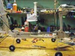
The model is just as you described. The coupling was done to match the rrpm of both rotors in hope that the lift would be approx. equal front and rear. I also wanted an advancing blade on each side for stability.

The rrpm in all phases of my testing never matched...usually by about 30 rpm less on the rear rotor. I assumed that it was because of airframe interferrence not allowing the same air flow to the rear rotor. I had read the NACA reports about this on real machinces and I tried all the things that was none by the NACA. I elevated the aft pylon, like on a Chinook, and the only improvement that I saw was in longitudinal stabilty. Then I tried a lower aft pylon and the same happened, lower rrpm, so I still assume that it's lower air flow through the rotor causing the difference.

In my reading, I read that tandems needed one advancing blade on each side of the airframe for stability and this is the major reason for coupling. It also allows me to shorten the airframe to reduce weight. I going to use the same 34% rotor overlap as the Chinook on this rebuild.

My next major question is, will my gearboxes be strong enough for all phases of flight? I feel that in normal cruising flight they are OK where torque is zero. In a prerotation or quick stops they may be weak...that's my question. It's the peak load as you suggested.
 
...usually by about 30 rpm less on the rear rotor
Joe,

the rear rotor is flying at a lower disk angle of attack than the front since the front rotor slightly bends the flow downward, see sketch in this post:
http://www.rotaryforum.com/forum/showpost.php?p=418615&postcount=11

This might also lead to the lower rrpm for the rear rotor. Do you have a separate collective for each rotor or do you vary the angle for longitudinal trim?
 
Buckwill,

Here a few pictures of the early version of the model. Picture #1 is the model on my work bench and #2 is some early testing at the Hobby Lobby test range, lol. In picture #1, I was testing the control concept which I tested in my shop in front of an industrial fan. I could get the front part of the model to lift off but not the rear. This was done before I had learn about differential collective. When I added this feature the model would float around like a hovercraft on my shop floor but lateral stability was poor. I just increased the wheelbase rather than adding advancing blades on both sides of the model (rotor coupling).
 

Attachments

  • P1200001.jpg
    P1200001.jpg
    33.7 KB · Views: 0
  • P4170001.jpg
    P4170001.jpg
    22.5 KB · Views: 0
Joe,

I have just added the paper "The Longitudinal Stability and Control of the Tandem-Rotor Helicopter" to the Technical Papers, Books, and Publications section.
Perhaps you can find some useful information there.

Cheers,

Juergen
 
Juergen,

Many thanks!! I'm hoping that when spring comes, I'll have a controllable model.

You've become a valued asset to the forum...Thank you!
 
Top