Coriolis...is it a force, or an effect?

Oop's no late Chuck already answered.
 
Of course a rock being twirled on a string by hand would be affected by holding it out of a car window. However, if the rock was traveling at typical rotor tip speed, say 500 fps (340 mph), the influence produced by a moving car would be negligible.

80:340 would be a 25% effect. I would call that negligible.
 
Accelerating over the ground when your rotors are not up to speed causes blade flapping. That is what I would expect in your example. Now speed up the blades/string and no problem. Right?

All In, Blade flapping in the context of a gyro accelerating before rotor RPM has spooled-up adequately is a totally different concept that a helicopters's purposely-designed-in features that create rotor system behaviors that compensate for dissymmetry of lift in forward flight.
 
All In, Blade flapping in the context of a gyro accelerating before rotor RPM has spooled-up adequately is a totally different concept that a helicopters's purposely-designed-in features that create rotor system behaviors that compensate for dissymmetry of lift in forward flight.
How much does a rotorblade weigh compared to a rock that could be twirled on a string and how does the drag of a rock compare with the drag of an airfoil?
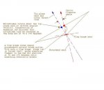
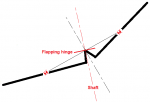
Here's a sketch that explains the need for drag hinges on a conventional rotor where the tip plane axis is not aligned with the hub:Coriolis...is it a force, or an effect?
 
Quote: But (if I'm understanding you correctly) that isn't the case in non-perturbed, unaccelerated, s/l flight, where the axis of rotation is indeed perpendicular to the tip-path plane... /Quote
On page 30 of his "Helicopter Dynamics" Bramwell derives formula 1.49 that gives the relationship between geometry, forces and moments of the aircraft and the angle between shaft and disk plane thus:
a1s=B1 - a1 = Hd/W - xCG/zCG + Mf/(W*zCG)
Let us asume that initially the rotor in plane force Hd devided by the aircraft weight W is exactly the same as the distance of the center of mass xCG devided by the height of the rotor head above the center of mass zCG and the fuselage cum horizontal stabilizer moment Mf is zero, then a1s=0 and the disk plane is perpendicular to the shaft, but if we now add any amount of Mf a1s will no longer be zero. Note that 1.49 was derived assuming unaccelerated straight and level flight. For a real helicopter where Mf usually is quite large the disk plane is perpendicular to the shaft only under rare combinations of load distribution and flight state, in general a1s is not zero even in unaccelerated straight and level flight, although it is probably small in most cases.
 
Last edited:
I don't doubt that the disk plane is usually not perpendicular to the shaft in fully articulated rotors, but I insist in that the axis of rotation (of the real rotation, not the shaft axis) is almost always perpendicular to the tip-path plane. There may be moments when it isn't, as when the blades, following a cyclic input, are in the process of finding a new plane of rotation, or when other de-stabilizing inputs throw the rotor system out of equilibrium, but 'in business as usual', the blade tips of a fully articulated rotor describe perfect, flat circles with a perfectly uniform rotation. As seen from that real-rotation axis (or as seen by a distant observer) the blades describe smooth circles, without flapping and without lead-lagging movements. Of course, the flapping- and lead/lag hinges are incessantly working all the time. That action of the hinges is, precisely, what makes the smooth circular motion of the blades possible...
 
Chuck,
Why individual undersling can not it delete the need for drag hinges with 3 blades or more ?
This divides the blade inertia by 12 isn't it ?
1144752
 
Interesting suggestion, JC.

Centrifugal force would impose a bending load on the blade that is not present with an underslung see-saw rotor.

The early Cierva Autogiros with fixed rotorheads and control via ailerons and elevators did not initially have drag hinges; Cierva believed flexibility of the tubular rotorblade spars would be sufficient, knowing the small amount of inplane motion. Unfortunately, one of the first machines crashed after losing a rotorblade but the English test pilot survived since the accident occurred at very low altitude.
 
Last edited:
Of course, and inertia is only divised by 4, not by 12
 
This is an interesting topic, and I appreciate the responses.
I'll have to review this thread when I have a little more time.
 
Accelerating over the ground when your rotors are not up to speed causes blade flapping. That is what I would expect in your example. Now speed up the blades/string and no problem. Right?
No, that's a different kettle of fish, and an extremely unfortunate, imprecise, informal use of the same term ("flapping") for a distinct behavior. The divergent blade behavior when you have lots of airspeed and inadequate rotor rpm is an issue for the typical Bensen-style rotor system, but is irrelevant for helicopters and for other gyros that still have "flapping" and lead-lag hinges. Only gyronauts use the term that way; a helicopter-only expert could be easily confused by that usage. (Gyro people have all sorts of bad linguistic habits, such as talking about multiple "rotors" when they really mean multiple "blades" in a single rotor, but that's another day's discussion . . . )

The fully-articulated rotor on an A&S 18A, which is always spun to greater than flight rpm before any airspeed is gained at all, cannot suffer from that dreaded first form of "flapping", but it has flapping and lead-lag hinges nevertheless to handle the motion of the blades with respect to the airframe. From some frames of reference, there is upward and downward motion of the blades as they turn (in stable un-accelerated forward flight) in each revolution. Whether you view the hinges as necessary to accommodate that perceived motion, or as just components of a universal joint when seen from the tip path plane, they are nonetheless necessary.

As to inquisitional heresy, there are many times when using heliocentric coordinates to describe the earth's motion is the appropriate choice, but if you're trying to aim an alt-azimuth mount tripod to take pictures of a sunrise or aim a solar cooker, the Ptolemaic view works just fine and can sometimes seem simpler in context.
 
Last edited:
At least three different meanings of the word "flapping" in the world of rotary wings
- Hit of the blades against the flapping stops
- Angle "β" of a blade above the bearing plane. The coning is a part.
- Angles "a" and "b" between the tip plane and the control plane (longitudinal and transverse)
 
Ironically, banging the flap stops with a stalled rotorblade is the only case where the term “flapping” is correct in a physical sense. Viewing the rotor tip plane off axis and believing relative blade motion is flapping is equivalent to believing the Sun rotates around the Earth.
 
At least three different meanings of the word "flapping" in the world of rotary wings
- Hit of the blades against the flapping stops
- Angle "β" of a blade above the bearing plane. The coning is a part.
- Angles "a" and "b" between the tip plane and the control plane (longitudinal and transverse)

The one I bolded... should really be defined as "Flapping - In the case of a helicopter in forward flight, The constant climbing and descending of each rotor blade, in relation the the air it is flying through, caused by helicopter design features or pilot input, to compensate for dissymmetry of lift."
 
Yes Bryan. It's true for the helicopter rotors forward tilted as well the gyro rotors tilted backward.
In steady cruising "a" is worth about 2 degrees and "b" is worth about one degree.
The lift is then the same for each side and thus the drag also. So, this is not the reason witch requires the drag hinge
 
A good video illustrating the Coriolis effect is this one, from a German TV production of the 90s, the 'Knoff Hoff Show'. It's voiced-over in Spanish:

 
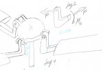
Did I get it right, Jean-Claude, that in your post #27 you proposed a design like the one I have tried to sketch here, where each blade has its own undersling?
undersling_rotor_crp.jpg
 
Yes, Juergen.
Undersling to each blade reduces four times the contrainte lead-lag when the drag hinge is ommited. But it is probably not sufficient for avoid the cracks to blade roots
 
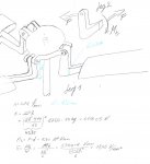
The blade root (the blue lines in fig.1) is indeed the critical point. I have cobbled together some ball park figures (see below) if the rotor rotates at 420 rrpm the bending stress at the blade root would be about 1800 N/mm² which is twice the tensile strength of even the best steels you could find for the application (the material must not be brittle, that would be to dangerous in such an application). But if the part is to be accepted by authorities you have to design for twice the rotational speed, which results in four times the stress as before or 7200 N/mm² which of course is outlandish.... sorry to rain on your parade...;-(
 

Attachments

  • Coriolis...is it a force, or an effect?
    undersling_rotor.jpg
    71.7 KB · Views: 7
Yes Juergen. Chuck and you are right
Bending stress due to the shifted centrifugal force is the main, here.
 
Top