piolenc
Joined 6/2007
- Joined
- Jun 27, 2007
- Messages
- 116
- Location
- Iligan City, Philippines
- Aircraft
- none
- Total Flight Time
- 13 (student)
Some time ago sombody on this forum was kind enough to put me in touch with Bill Piper. My problem was that I have no, or very limited and expensive access to aircraft-grade structural tubing in my outpost of civilization in Mindanao, but there's plenty of high-grade sheet metal. Mr. Piper had, years ago, built a successful open gyro structure of riveted sheet metal. When I contacted him, he kindly gave me all the details he had available, and permission to post them here in case others might benefit. I'm finally getting around to doing that. What follows is two email messages from him:
--------------------------------QUOTE---------------------------------
Dear Mr. Piolenc.
I was flattered by your interest in my gyro. Unfortunately I never drew plans for the machine that other people could use. I designed and built the original version from layout drawings and sketches in the late 1950s, initially as a towed glider which my partner and I used to learn to fly it. I modified it later to add a McCulloch engine. We flew it until 1998 when it was badly damaged by a ground loop after landing, for unknown reasons. I have not rebuilt it because of my age. The gyro had almost 300 hours of flight time.
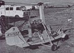
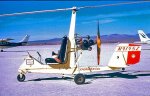
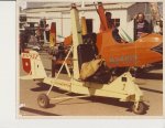
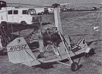
About all I can do to help you is to attach two photos and describe the construction. The horizontal fuselage is made of .040" (inches) thick 2024-T3 aluminum sheet formed into two channels. The upper channel is 5" wide with tapered vertical flanged. The lower channel is slightly narrower so that it nests inside the bottom of the upper channel. The flanges of the lower channel are a constant 1" high, pointing upward. The flanges of the two channels are riveted together to form a monocoque box which is 5" wide and a height varying from 7" at the center to 3"" at each end. The length is about 107." There are nine frames inside the box to maintain its shape. They are made from rectangular pieces of 2024-T3 sheet with bent flanges on all four sides so that they can be riveted to the box.
The mast construction is similar to the horizontal fuselage except that the lower part is reinforced to support the weight, thrust and vibration of the engine. It is joined to the horizontal fuselage with riveted gussets on each side. The engine mount is mostly aluminum angle, as is the support for the seat. The superstructure at the front of the fuselage is also .040" aluminum sheet. It originally mounted the tow hitch when the machine was a glider and is the mount for the instruments. The main landing gear is mostly 1" diameter SAE 4130 steel tubing. The upper struts have telescoping upper ends with die springs inside to absorb shocks.
Obviously this construction is vastly more difficult to fabricate than a typical Bensen-type gyro which is primarily lengths of 2" square aluminum tubing bolted together with gussets. My design requires precision aluminum forming and the driving of hundreds of 1/8" solid rivets with a pneumatic rivet gun. I wanted a gyro design much more sophisticated than Bensen's, but it took much longer to build.
I hope this information is of some help. I wish I had more to offer. Good luck with your project.
William Piper
Dear Mr. Piolenc:
If you wish to post the information on my gyro to the Rotary Wing Forum, I don't mind. Remember that this design is about 50 years old and photos of the machine have been in Rotorcraft magazine many times, as well as an article.
You ask about my use of solid rivets. They are cheaper and stronger than blind rivets. At the time I designed the gyro, in the late 1950s, blind rivets were a rarity and much more expensive than MS20470AD4 rivets. To buck them, I had 3 1/2" dia. holes in the bottom of the horizontal fuselage and the aft side of the mast between the frames. The holes were covered by plates to keep out bugs and dust.
Except for the rotor head and landing gear, only cursory stress analysis was needed since the stresses in the sheet metal were far below the yield strength of the 2024-T3 aluminum skins.
I first used this type of construction in the design of an item of ground support equipment for an Air Force fighter jet. It worked well.
I hope this information answers your questions. If you need more, send e-mail
Regards, William Piper
--------------------------------QUOTE---------------------------------
Dear Mr. Piolenc.
I was flattered by your interest in my gyro. Unfortunately I never drew plans for the machine that other people could use. I designed and built the original version from layout drawings and sketches in the late 1950s, initially as a towed glider which my partner and I used to learn to fly it. I modified it later to add a McCulloch engine. We flew it until 1998 when it was badly damaged by a ground loop after landing, for unknown reasons. I have not rebuilt it because of my age. The gyro had almost 300 hours of flight time.
About all I can do to help you is to attach two photos and describe the construction. The horizontal fuselage is made of .040" (inches) thick 2024-T3 aluminum sheet formed into two channels. The upper channel is 5" wide with tapered vertical flanged. The lower channel is slightly narrower so that it nests inside the bottom of the upper channel. The flanges of the lower channel are a constant 1" high, pointing upward. The flanges of the two channels are riveted together to form a monocoque box which is 5" wide and a height varying from 7" at the center to 3"" at each end. The length is about 107." There are nine frames inside the box to maintain its shape. They are made from rectangular pieces of 2024-T3 sheet with bent flanges on all four sides so that they can be riveted to the box.
The mast construction is similar to the horizontal fuselage except that the lower part is reinforced to support the weight, thrust and vibration of the engine. It is joined to the horizontal fuselage with riveted gussets on each side. The engine mount is mostly aluminum angle, as is the support for the seat. The superstructure at the front of the fuselage is also .040" aluminum sheet. It originally mounted the tow hitch when the machine was a glider and is the mount for the instruments. The main landing gear is mostly 1" diameter SAE 4130 steel tubing. The upper struts have telescoping upper ends with die springs inside to absorb shocks.
Obviously this construction is vastly more difficult to fabricate than a typical Bensen-type gyro which is primarily lengths of 2" square aluminum tubing bolted together with gussets. My design requires precision aluminum forming and the driving of hundreds of 1/8" solid rivets with a pneumatic rivet gun. I wanted a gyro design much more sophisticated than Bensen's, but it took much longer to build.
I hope this information is of some help. I wish I had more to offer. Good luck with your project.
William Piper
Dear Mr. Piolenc:
If you wish to post the information on my gyro to the Rotary Wing Forum, I don't mind. Remember that this design is about 50 years old and photos of the machine have been in Rotorcraft magazine many times, as well as an article.
You ask about my use of solid rivets. They are cheaper and stronger than blind rivets. At the time I designed the gyro, in the late 1950s, blind rivets were a rarity and much more expensive than MS20470AD4 rivets. To buck them, I had 3 1/2" dia. holes in the bottom of the horizontal fuselage and the aft side of the mast between the frames. The holes were covered by plates to keep out bugs and dust.
Except for the rotor head and landing gear, only cursory stress analysis was needed since the stresses in the sheet metal were far below the yield strength of the 2024-T3 aluminum skins.
I first used this type of construction in the design of an item of ground support equipment for an Air Force fighter jet. It worked well.
I hope this information answers your questions. If you need more, send e-mail
Regards, William Piper