Electronic Governor

One of the biggest difficulties with governors is that the control parameters need to be set up for the system you are trying to control. The inertia of a car is orders of magnitude higher than the inertia of a rotor, which means that it is very unlikely that a governor optimised for a car will work well in a helicopter. A two stoke engine behaves very differently to a four stroke, engines with a flat torque curve are much easier to control than high performance engines with a peaky torque curve.

I built a governor for a Mosquito Air and it took me about 10 hours of tuning to get it to work well over all flight conditions. If the engine is loaded it's relatively easy, when the engine is lightly loaded it is a lot more difficult. Even the R22 governor sometimes hunts under lightly loaded conditions.

I then put the same governor on a Mosquito XE. The XE is very similar to the Air, same engine but slightly longer blades. The slightly longer blades changed the system enough to have to fine tune the controller again.

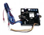
The controller I built was microprocessor based using fuzzy logic. The control parameters (which were set up in software) had to be set up accurately to achieve stable operation under all flight conditions.

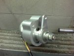
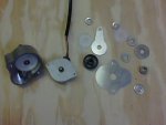
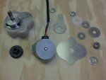
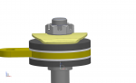
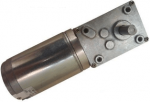
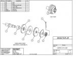
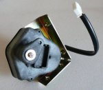
The second part of the governor is the actuator. The design of the actuator depends a lot on the design of the throttle mechanism used, engines using cables and Bing 54 carbs are tricky because of the very strong return springs used in the carbs. A R22 uses mechanical linkages with no spring return which is much easier.

Robinson would have spent a long time optimising their governor for their machine, be very careful of taking just any old box which has "governor" written on it and expecting it to work first time in a helicopter. John knows what can happen if you do that...
 
Heli Gov

Heli Gov

Hi All against my better judgment I will give away my secrets. here is a link to the controller that I might use.http://www.partsfortechs.com/asapca...98647-governor-control-kit-stepper-p-534.html I bench tested it but not installed yet might work might not work someone want to give it a try that will save me the time of doing it. you will need to modify the stepper gear box from stock to how ever you need it to be on your engine.it uses a fixed 50 or 60HZ input use a Dakota digital pulse converter to match up to the speed of your sensor. if it works great you saved me the time of testing it.

Doug

Just my uneducated opinion
 
Hi All

You mean you need one of these.
sorry you can not buy one that looks like this you need to build it yourself.
Doug

Doug the actuator is what were looking for!!!! That you have in this picture??? There's plenty of controller to choose from.. I'll be glad to be the test dummy for you!!!!!!!
 

Attachments

  • 100_0335.JPG
    100_0335.JPG
    31.5 KB · Views: 3
Last edited:
On the 50Hz setting, 7 magnets on the main shaft will give you 428RPM, 6 magnets will give you 500RPM.

On the 60Hz setting, 7 magnets on the main shaft will give you 515RPM, 6 magnets will give you 600RPM.

I wonder how many % RPM offset can one adjust the governor setting, or is it fixed? What are the 3 trimpots on the module used for?

Cheers,

F.
 
What are the 3 trimpots on the module used for?

Cheers,

F.

Click on the "installation sheet" in the link.

I wonder how a stepper drive would compare to a current source?
The old analog electronics has my vote over a micro controller in this situation. (I do love micros though)

Cheers Cam.
 
The old analog electronics has my vote over a micro controller in this situation.

Amen !! Something built up from discreet components. Bulletproof......

I wonder if it is worth the trouble to share development circuitry on this forum? I have never seen electronic circuits for aviation purposes being discussed. Most guys seem to tinker with the mechanics and power circuit electrics only.

Cheers,

F.
 
Gov stepper motor

Gov stepper motor

The control unit has adjustments for droop gain and stability.. the frequency's are fixed either 50 of 60 Hz that's why you may need a Dakota digital converter to adjust your input frequency if you can not get the proper amount of input pulses to match the 50 or 60 HZ The white gear in the picture is a 48 tooth 32 DP the black gear comes in the generac stepper motor. the through shaft is a AN5 bolt the gear is pinned to the shaft. the bearing is just a regular old .312 ID sorry don't remember what the OD is .750??? does not make a difference just make your bearing retainer to fit there are Derlin washers on each side of the arm springs are 2 5/16 lock washers will switch to a wave washer lock washers are temporary. fender washer is 1.125 Dia. piviot length on the arm is 1.400 total width of the gear box is 1.0 in. depth of where the gears are .625 plus a step where the gear hub is. attached with the pictures is a BobCad dwg file of the gear box not sure all what Cad programs will open it.
can not post the cad file wont up load John I'll send it to you and others on request

Have fun


Doug

Just my uneducated opinion
 

Attachments

  • 101_0335.JPG
    101_0335.JPG
    19.7 KB · Views: 9
  • 101_0336.JPG
    101_0336.JPG
    21.9 KB · Views: 9
Last edited:
The control unit has adjustments for droop gain and stability.. the frequency's are fixed either 50 of 60 Hz that's why you may need a Dakota digital converter to adjust your input frequency if you can not get the proper amount of input pulses to match the 50 or 60 HZ The white gear in the picture is a 48 tooth 32 DP the black gear comes in the generac stepper motor. the through shaft is a AN5 bolt the gear is pinned to the shaft. the bearing is just a regular old .312 ID sorry don't remember what the OD is .750??? does not make a difference just make your bearing retainer to fit there are Derlin washers on each side of the arm springs are 2 5/16 lock washers will switch to a wave washer lock washers are temporary. fender washer is 1.125 Dia. piviot length on the arm is 1.400 total width of the gear box is 1.0 in. depth of where the gears are .625 plus a step where the gear hub is. attached with the pictures is a BobCad dwg file of the gear box not sure all what Cad programs will open it.
can not post the cad file wont up load John I'll send it to you and others on request

Have fun


Doug

Just my uneducated opinion

Not in the least uneducated. May I ask where you bought that actuator?

Instead of using a clutch in the actuator like the R22, what do you folks think about using a spring system that allows the pilot to override the governor? Same purpose, but simpler. Would like your thoughts on this versus using a slipper clutch.
 
I suppose you could also just use a stepper motor that has low enough torque to be overridden, seems like that would keep it simpler?
 
The control unit has adjustments for droop gain and stability.. the frequency's are fixed either 50 of 60 Hz that's why you may need a Dakota digital converter to adjust your input frequency if you can not get the proper amount of input pulses to match the 50 or 60 HZ The white gear in the picture is a 48 tooth 32 DP the black gear comes in the generac stepper motor. the through shaft is a AN5 bolt the gear is pinned to the shaft. the bearing is just a regular old .312 ID sorry don't remember what the OD is .750??? does not make a difference just make your bearing retainer to fit there are Derlin washers on each side of the arm springs are 2 5/16 lock washers will switch to a wave washer lock washers are temporary. fender washer is 1.125 Dia. piviot length on the arm is 1.400 total width of the gear box is 1.0 in. depth of where the gears are .625 plus a step where the gear hub is. attached with the pictures is a BobCad dwg file of the gear box not sure all what Cad programs will open it.
can not post the cad file wont up load John I'll send it to you and others on request

Have fun


Doug

Just my uneducated opinion


Thanks Doug!!

I will get started on this project next week once I get all the parts ordered. Yes I got the cad drawing. Once a gain thanks for your help.

Is this the proper decoder I need to make the signal work???????????????????????
I will be posting the progress here as we go..

http://www.dakotadigital.com/index.cfm/page/ptype=product/product_id=126/
 
Amen !! Something built up from discreet components. Bulletproof......

I wonder if it is worth the trouble to share development circuitry on this forum? I have never seen electronic circuits for aviation purposes being discussed. Most guys seem to tinker with the mechanics and power circuit electrics only.

Cheers,

F.

I thank its worth sharing!! Electronics are new to me.. I want to learn as much as I can about circuitry.... There are some really smart people on this forum and I sure wish they would chime in and help people more often...
 
Digital converter

Digital converter

Hi John thats the one I have. I found out a long time ago that it is easier to find the electronics that will work for what you are doing. If you cant find what you want then you build.

Doug
 
Hi All,

My actuator under construction. I have started with the slipper clutch design. I plan to take a COTS DC motor with worm gear reduction drive, and replace the output shaft with my shaft.

Cheers,

F.
 

Attachments

  • Slipper_clutch_assy.png
    Slipper_clutch_assy.png
    26.3 KB · Views: 12
  • Untitled.png
    Untitled.png
    18 KB · Views: 12
  • Untitled.jpg
    Untitled.jpg
    29.3 KB · Views: 12
Last edited:
Francios,
Nice looking start for a clutch, but I thought you were using the Robinson actuator?? I got all my electron components ordered. I went to the boneyard for a frame to use for the mock up. I than broke into the new unassembled kit we have and started putting the collective together just as it is on my MH-1. Once I get that all put together, and my electronic parts will be here on the 26th. When they get here I will start designing the mount and the stepper motor housing. I want it to mount right on the collective using the three points given on the collective which will require some fancy CNC machining. That’s right up my alley. Then I can get the actuator arm made to the correct length. Than I can design the slipper clutch around the actuator arm. I also bought some electronic testing equipment like this signal generator. I can’t wait to get started…
 

Attachments

  • Generac Controler.jpg
    Generac Controler.jpg
    32.2 KB · Views: 12
  • Stepper Motor.jpg
    Stepper Motor.jpg
    29.9 KB · Views: 12
  • DSC_0001 680.jpg
    DSC_0001 680.jpg
    51.6 KB · Views: 14
  • DSC_0002 680.jpg
    DSC_0002 680.jpg
    29.7 KB · Views: 14
Some random thoughts and ideas on a helicopter engine governor, some already discussed in this thread.

DC motor with gearbox like Robinson.
alternately, consider stepper motor and controller. (Generac)

slip clutch to allow manual twist grip override

"governor off" amber indicator

gov on/off toggle switch on cyclic

sensing of engine speed, not rotor speed

governor not active until 80%

"bump" switch on cyclic to inc/dec rrpm within the green band. Pic here http://www.helicoptersonly.com/contents/en-us/d217.html

incorporate throttle position sensor with an indication when max throttle has been reached by governor, such as when carb ice causes throttle creep.

similarly, detect when governor calls for power reduction and pilot grips too tightly, preventing change. I read of at least one case of a student gripping twist grip too hard, causing an overspeed on runup leading to the tail shaft entering one of the known R-22 whirl modes and destroying the tail.

PID (proportional/integral/derivitive) governor algorithm that is tuned for operation at the typical >=75% power load point of an aircraft engine, not the < 25% load point of the auto cruise controls.
This avoids hunting and surging.

Provide a jack for plugging in an external signal generator for testing and calibrating in helicopter.

Info on modifying a robinson gov
http://www.bart.gen.nz/safari/governor-200404.doc

'Note that the use of the PID algorithm for control does not guarantee optimal control of the system or system stability.' from http://en.wikipedia.org/wiki/PID_controller

An adaptive PID algorithm implemeted on a microcontroller may offer some benefits as discussed in this article:
"A Simple PID Controller with Adaptive Parameter in a dsPIC"
http://www.aedie.org/9CHLIE-paper-send/337_CHAINHO.pdf

Note that the Futaba GV-1 r/c governor claims to use an adaptive PID algorithm.


Yes all of that will be incorporated into the way it operates. I also forgot to post a picture in signal generator and the signal convertor. I will be using the six tooth reluctor on the engine to control the governor.
 

Attachments

  • Signal Generator.jpg
    Signal Generator.jpg
    21.2 KB · Views: 10
  • Dakota Digital.jpg
    Dakota Digital.jpg
    34 KB · Views: 12
  • 6 TR.jpg
    6 TR.jpg
    29.4 KB · Views: 14
Francios, Nice looking start for a clutch, but I thought you were using the Robinson actuator??

Hi John,

Yes, for now I'm using a Robinson actuator, but as you know, they are EXTREMELY expensive. If I wish to replicate my governor for someone else, I need a replacement that it functionally similar, but that would only cost a hundred or so dollars.

Another reason is I'm step by step, ridding my build of all the OEM stuff. You will understand where I'm coming from. I just last week knocked up a set of anti-torque pedals, to replace the original castings. Firstly to get away from the OEM design, secondly because I hated the ankle twisting motion, I prefer the toe pressing motion. I still need to include some heel rests onto the frame.

For those that noticed, excuse the surface rust that has since accumulated, I'm too slow to strip the pedals off and blast them.

Nice reluctor, but why take your signal off the engine? Is it not better to take it off the mainshaft? What about potential clutch slip? I've always thought of it as an RRPM governor, not an engine governor.

Cheers,

F.
 

Attachments

  • New Style Pedals.jpg
    New Style Pedals.jpg
    38.9 KB · Views: 9
Last edited:
Francios,
The Robinson governor is expensive that’s why I never bought one. Also I know we can build one that does the same thing the Robinson one does for pennies on the dollar. My six tooth reluctor is tied to the spindle shaft that’s bolted to the crank shaft and not the clutch. If the clutch starts slipping you have other problems not related to the governor!!! Get ready for a full down and seat cleaning.. I want this thing to be simple and to the point and universal to use on other helicopters as well. The signal comes from the engine which drives the rotor. No engine, no rotors, not good!! Your pedals are nice but shouldn’t you have made the top part stick forward so your foot isn’t on the up support, what you got works the same, you have just lost the look!!
 

Attachments

  • 6 TR.jpg
    6 TR.jpg
    29.4 KB · Views: 7
Hi John .
Is it ok if I come to visit you and Rick around Bensen days ?? You eagle eyed flyer!!!!!.
Regards.
LUCIANO
Ps. I will ring you soon.
 
Top