Xenon rotor attachment holes deformed =(

Phil,
I hope you trust that my questions are not intended to affect AT company reputation - I candidly wish you further progress. This is just technical discussion, no more.

I know this is just a technical discussion, and I am here to answer all your possible questions as well as I can.

The Institute of Aviation in their tests checked the rotor with a double safety margin. For our rotor for the weight of 600kg and 500 rev / min, for the rotor to I-28 (Institute of Aviation gyro) test was for 740kg and 430 rev / min (bolts diameter 10). Those tests were made without an internal bar or any reinforcement and after nothing was wrong.

Michał Trendak
 
As I could understand those tests covered static spanwise tension only and didn't cover varyable loads which apply while rotor is in transitional stance when it changes coning angle while applying/removing Gs.

I probably missed something but imitating of 500 rrpm tension doesn't look like double safety margin. Especially if this imitation doesn't cover coning condition. Normal level flight rrpm for 8.6 m Xen rotor is 350-370 in gross and it's nothing special to see 480-490 rrpm on maneuvering. That is not that close to the reacheable max rrpm limit. So if we agree for 1.5 safety margin then tests should be done for at least 600 rrpm loads.
 
As I could understand those tests covered static
spanwise tension only and didn't cover varyable loads which apply while
rotor is in transitional stance when it changes coning angle while
applying/removing Gs.

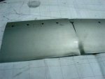
I visited the Institute of Aviation some time ago and discussed this subject
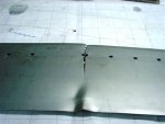
with them. They decided to use some pre-coning on their I-28 rotor
as you can see in this image (app. 3 deg.):

Xenon rotor attachment holes deformed =(


The load testing was done only for static span-wise pull, as you expected.

I probably missed something but imitating of 500 rrpm tension doesn't
look like double safety margin. Especially if this imitation doesn't cover coning
condition. Normal level flight rrpm for 8.6 m Xen rotor is 350-370 in gross and
it's nothing special to see 480-490 rrpm on maneuvering. That is not that close
to the reacheable max rrpm limit. So if we agree for 1.5 safety margin then tests
should be done for at least 600 rrpm loads.

The Institute was testing the blades for their bigger, 9.4m rotor.
They made a test for the 8mm holes. They pulled the rotor blade with the
force of 8 tonnes (this corresponds to a centrifugal force of the rotor
rotating 430 rev / min).

If we take the formula:

Xenon rotor attachment holes deformed =(


then the centrifugal forces for the 8.4m rotor would be just 7.2 tonnes.

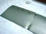
They showed me the rotor samples with 8mm holes they pulled
up to 24 tonnes, when they eventually started "floating" and broke.

You can back calculate the rpm corresponding to those forces,
but I do expect, they are well in excess of 600rpm.

According to my calculations it is 785rpm, when the rotor blades brake,
but I might be wrong. :)

Assuming the max. rpm you can reach in flight is 370rpm,
the safety factor is 2.1 not 1.5...

And, yes, they didn't use any insert.
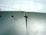
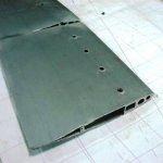
Looking at the detailed images, you can see that the rotor failed
on the last bolt, so the insert wouldn't change much, if not reaching
beyond the last bold and being firmly bonded to the rotor skin.
Then the blade would probably fail at the end of the insert.

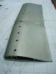
This is also an interesting observation regarding the number of bolts
that should be used. If 5 or 9 in doesn't change much, the blade
will fail on the last one. Any more holes can only weaken the blade root.
 

Attachments

  • Xenon rotor attachment holes deformed =(
    IL 2012 046.jpg
    22.4 KB · Views: 1
  • Xenon rotor attachment holes deformed =(
    IL 2012 048.jpg
    25.7 KB · Views: 1
  • Xenon rotor attachment holes deformed =(
    IL 2012 049.jpg
    19.4 KB · Views: 1
  • Xenon rotor attachment holes deformed =(
    IL 2012 050.jpg
    25 KB · Views: 1
  • Xenon rotor attachment holes deformed =(
    IL 2012 053.jpg
    22.8 KB · Views: 1
  • Xenon rotor attachment holes deformed =(
    IL 2012 054.jpg
    20 KB · Views: 2
Last edited:
Paul,

Thanks for the add-on about those tests. I'm still curious how far they didn't see a difference between loads in subject tests and real loads. Flat hub bar would redistribute loads between bolts and holes when lift appears. Particularly between upper and lower holes. This can completely change the picture and safety edge.

This is a photo of how J.McCutchen tested his SkyWheels rotors:
Xenon rotor attachment holes deformed =(
 
Last edited:
Thanks for the add-on about those tests. I'm still curious how far they didn't see a difference between loads in subject tests and real loads. Flat hub bar would redistribute loads between bolts and holes when lift appears. Particularly between upper and lower holes. This can completely change the picture and safety edge.

They did the calculations of the lift conning vs. centrifugal force
and calculated the pre-conning of the hub bar needed to eliminate
the flexing force by standard flight rpm.

Of course, there will be some negative blade flexing below this rpm,
(blade flapping) and some positive flexing by extreme manoeuvres.
But this flexing will be compensated by the rapidly increased
centrifugal force. Proper angle balances the flexing forces out.
What remains are pure blade pull forces.

Their bottom line: flexing forces are negligible by properly pre-coned
hub bar and therefore were not taken into consideration.
 
Now let's make couple steps back and remember that Xen hub bar has no preconing..
 
Now let's make couple steps back and remember that Xen hub bar has no preconing..

You said that.

Also the AutoGyro GmbH, Aircopter,
Averso rotors do not have conning.

I am not sure about SportCopter.

AutoGyro GmbH learned the lesson the hard way with some
blade fatigue fractures and eventually made the hub bar
more flexible, which could be seen as a poor substitute
of the conning.

I think, some more knowledgeable people should chime in.
 
First off, the coning angle during steady state flight conditions (i.e., such conditions during which the rotor rpm are constant) is independent of gyro weight or loading. It is solely determined by the ratio of lift to centrifugal force. Both of which depend on rpm in the same manner, which makes their ratio, i.e., the coning angle, independent of rpm.

However, when abruptly entering a sharp turn the rotor will take a few seconds to spin up to its higher rpm. During that time span the centrifugal force will be lower than required in steady state and hence the coning angle will be greater.

The most significant means to alleviate undue bending stress concentrations in the rotorblades is to have a gradual taper of stiffness from the rotor hub to the free blade. Any jumps in stiffness as would result from a very stiff hub bar with no taper, lead to high bending stresses near the end of the hub and would result in stress cracks around the last bolt holes in a cord-wise direction on the bottom of the blade.

I did detailed simulations of the Averso rotor (since the ArrowCopter uses this rotor). Those numerical and FEM calculations were then backed up by experimental measurements using strain gauges and found to agree to within 4%. Our result is that the Averso hub and hub bar is sufficiently flexible so that no worrisome stress concentrations arise.

AutoGyro's new rotor hub bar now has taper as well as pre-cone.

Greetings, -- Chris.
 
...
AutoGyro's new rotor hub bar now has taper as well as pre-cone.
.

Chris, thanks for your expert's comment.

Do you know what is the pre-cone on their rotor hub?

Does your Averso rotor also have a pre-cone?
 
You said that.

Also the AutoGyro GmbH, Aircopter,
Averso rotors do not have conning.
The first MT03 used aircopter bladesets which were not coned. Since 2006 they make their own heads which are coned.

AutoGyro GmbH learned the lesson the hard way with some
blade fatigue fractures and eventually made the hub bar
more flexible, which could be seen as a poor substitute
of the conning.
The hubbars were coned on the gyros with damages.
However, you could force them out of their pre-coned angle by very forceful and sudden control movements, where the rotor did not have time to spin up to the new load.
They did extensive testing with stress gauges and were afraid to fly so forcefully, until they finally reached results. So not a standard type of usage. I know only very few who had these problems, and they really flew like rodeo cowboys (the ones on the bulls).
Since last year they now use a tapered stepped hubbar which gets thinner towards the ends to cater for the bull-riders.

Kai.
 
Last edited:
The dynamic state when the centrifugal force cannot balance the lift force
is really worrying.

I have seen several Xenons hot-dogging, never thought about this problem.

There should be probably really much more analysis done of such state.
 
Now let's make couple steps back and remember that Xen hub bar has no preconing..

Another step back, and a question:
how much of "dynamic" flying has this machine seen in her life?
 
Pavel,

I believe the AutoGyro hub has a pre-cone angle of 3.5°. What I don't remember with certainty is whether this number is for the old or new hub.

In the new hub the pre-cone angle was increased and the stiffness carefully tapered.

The Averso hub has no built-in precone. It makes up for this by having favorable bending stiffness which allows it to bend sufficiently to prevent overly high bending loads on the blades.

-- Chris.
 
The design of the Averso hub bar is excellent.

Its octagonal shape reduces both stiffness and internal stresses in the hub.

Even in steady flight with constant coning angle, there is a periodic flexing at root ends as the load center of the blade shifts inboard to outboard with rotation.
 
...Even in steady flight with constant coning angle, there is a periodic flexing at root ends as the load center of the blade shifts inboard to outboard with rotation.

Yes, you're right. But the shift in load distribution has most of its effect in the outboard half of the blade and doesn't contribute terribly much to bending stresses near the root.

-- Chris.
 
Unfortunately it's still waiting to be done. Owner of this Xenon is too busy to initiate this job. Hopefully we have it fixed before spring comes.
 
Top