Help - Rotor Head Design - Double or Single Bearing and undersling?

There are two types of head bearings, a standard fill and a max fill (more balls), will the max fill take a higher "bending load" than the standard fill? Also, is it acceptable to use a bearing with a brass cage?
 
As for your blade teeter, if you use the 5.750" high teeter with the 6.187" high tower, that will give you a 14 degree teeter. My calculations show me that you would have about 0.812" from the bottom of the hub bar to the top of the teeter stop block, is that correct? If so, then that is WAY too much! You only want a 8 degree teeter.

If you wanted to use the 5.750" Teeter, then you would need to make your towers to 5.843" high.

Even if you adjusted the towers, using the 5.750' teeter block will move your teeter/CoM intersection point out to 8'-5" from Center of Rotation, with a 3 degrees coning!! Holy cow! Using the 3.69 degrees of coning is too much coning, but that will get you closer at 6'-9" from Center of Rotation. Still not close enough, but we are guessing without a known Center of Mass.

If you make the tower height to 5.843", you'll have the correct teeter for the 5.750" teeter height.

As for the rotorhead bearing, I don't know what you have, but I always used the MSC 5206CZZ. The dynamic load rating of this bearing is 6,660 lbs, but that was at a speed rating of 7000 RPM, and I believe a 20,000 hour life at that load. It is double row angular contact, and made for side and twisting loads. So, for the little work we are doing with it, at double your weight it is still way strong enough.
 
OK - thanks again for all the input.

Unfortunately, C Beatty's level of expertise is far above my own, and just when I am about to understand it, other concepts come into play, and I am lost...

Dennis, I must have given you bad coordinates...

teeter block: 5.75 inches from BOTTOM of hub bar/teeter block to center of teeter bolt hole (this is the measurement from center of teeter bolt hole to bottom of teeter block and hub bar as connected, and shown on your pic.)

teeter tower: from top of stop block to the center of the teeter bolt hole on the towers is 6.1875"

height between bottom of hub bar and top of stop block is .4375" (7/16)

The 3 degree bend starts 2.5" from the center of the teeter block, with the stop block extending out 2.8125 inches from the same point.

Does that change the teeter angle any? i think Joe Terminella told me it was originally set at 9 degrees for some reason. My recollection could be wrong...

I'm trying to do the geometry right now, but it's been awhile since I did that...

I will add the dimesions to your picture, and post it.
 
Here's the pic

Here's the pic

Picture with figures...
 

Attachments

  • Rotorhead.jpg
    Rotorhead.jpg
    74.5 KB · Views: 0
OK - thanks again for all the input.

Unfortunately, C Beatty's level of expertise is far above my own, and just when I am about to understand it, other concepts come into play, and I am lost...

Dennis, I must have given you bad coordinates...

teeter block: 5.75 inches from BOTTOM of hub bar/teeter block to center of teeter bolt hole (this is the measurement from center of teeter bolt hole to bottom of teeter block and hub bar as connected, and shown on your pic.)

teeter tower: from top of stop block to the center of the teeter bolt hole on the towers is 6.1875"

height between bottom of hub bar and top of stop block is .4375" (7/16)

The 3 degree bend starts 2.5" from the center of the teeter block, with the stop block extending out 2.8125 inches from the same point.

Does that change the teeter angle any? i think Joe Terminella told me it was originally set at 9 degrees for some reason. My recollection could be wrong...

I'm trying to do the geometry right now, but it's been awhile since I did that...

I will add the dimesions to your picture, and post it.

Yes, I read your dimensions wrong. I did it again and with the dimensions you do have an 8 degree teeter with the 5.750" teeter and 6.187" tower.

No, where the bends are do not change the angles, they are far enough out.

I still would like to know the true CoM for an accurate calculation.
 
Thanks, Dennis. I appreciate your time and help.

I will measure the CoM of the blade, as that is the best that I can do from my garage....

Will that get you in the ball park? I think Chuck mentioned that the 27' DW's have a 2 lb. tip weight...
 
Thanks, Dennis. I appreciate your time and help.

I will measure the CoM of the blade, as that is the best that I can do from my garage....

Will that get you in the ball park? I think Chuck mentioned that the 27' DW's have a 2 lb. tip weight...

Tip weight don't matter, it's the overall CoM I need, and with that, I'll not just be in the ball park, but we'll be on home plate.

I'll save my drawings and calculations for when you do have it.
 
For a twisted blade, the mean pitch is that at 0.7 radius. .
I think I'm done poorly understood.
The local lift each slice of blade being proportional to R gyration exp.2, the result should not be at 0.75 R for a blade without twisting? And perhaps to 0.8 R if the blade is twisted? In addition, the centrifugal force on these slices of blade are in proportion to R gyration. The result should not be within 2/3 of blade? If so, the cone angle will be greater at the tip, and less at the center, no?
 
Spencer,

GyroRon test flew your machine before you purchased it, if you are still running the same blades and head as then, I would ask him what the vibration levels were before messing with the undersling.
 
OK, I figured the teeter angle as this, using online calculators:

Without the 3 degree bend starting 2.5 inches from center of hub bar:

Teeter angle came out to : 8.03 degrees

With the 3 degree bend figured in at the 2.5" mark the teeter angle comes out to: 9.02 degrees.

According to the numbers, the 3 degree bend DOES have an impact!! (3.62" out from the center of the hub is where the hub bar will make contact. Since the bend starts at 2.5 inches. you have a slope up of 3 degrees for 1.1239 inches, equating to a .0589" increase in travel. In other words, the 3 degree bend acts like the teeter height is only 5.69" instead of 5.75", and that adds a degree to the teeter angle.)

I measured teeter angle from the center of the teeter bolt to the center point of the hub as the hub bar hit the stop block. I originally used the stop distance (2.8125") and the distance between the hub bar and the stops (.4375"), but the teeter angle came out the same no matter where I put the teeter bolt, so I went back and figured it out using the angle from the teeter bolt to the hub center as the hub bar made contact with the stop.

I know, I know, confusing without a picture....

Can anyone verify my numbers?

Also, is 8 or 9 degrees OK for a flap angle?

formulas calculated at: http://www.carbidedepot.com/formulas-trigright.asp
 
Alan, GyroRon Awad flew it and said that it flew perfectly, albeit underpowered.

I am not intending on messing with the undersling yet, but since I have been given the advice to swap the single bearing head for a double bearing head, I need to give Ernie the right numbers. Joe T used an original RFD single bearing block, then manufactured a set of teeter towers for the 27' DWs.

Since I am probably going to order a new RFD double bearing with RFD teeter towers, I am trying to ensure that I have the right undersling.

Right now, If I keep the rotor head as is, I will still need to machine some holes for the anti-flap brackets, as the ones on there right now are too short (this is how this whole issue came up)

I am still torn on whether to go double or single bearing head, until I get more info.
Mike Schallman and Dennis Fetters say keep it, Ernie Boyette says change it, and Chuck B said basically that I was nearing the spec bearing limit...

So I am still undecided.

The safety-conscious person in me says "Do what Ernie recommended and be done with it", the cheap-a$$ back-yard mechanic and gyro builder in me says "Aw screw it, it'll be fine as is" and the budget guy in me says "I would rather spend the $500 on something else, as this expense will cause me a$$ pain with the wife."

So, as you can see, I'm just screwed up.

Thanks for listening.

Also - anyone have an idea how far the anti-flap brackets should hang above the hub bar? 1/4" 3/16" 1/8" more? less? I know they should make contact before the blades hit the stops, but HOW MUCH earlier?
 
According to the numbers, the 3 degree bend DOES have an impact!!

It will depend on the radius of the bend. I was guessing by remote control what it was, and with the radius I used, it was far enough out.

I would not be afraid of the 9 degrees. The only time you'll use it is when you're flapping the blades. So don't do that.
 
Spencer,

Here is how you can get the center of mass of the blade for Dennis. What this is, is, a fixed-wing commercial pilot weight-and-balance problem. So you need to know:

  1. The weight of the blade (a simple measurement)
  2. The center of mass of the blade (balance it on a fulcrum and measure)
  3. The weight of half of the hub bar (weigh the bar and bolts and divide by two).
  4. The center of mass of half of the hub bar (this is a bit harder to do, but unless the hub bar has unusual weight distribution -- that is, the hub bar isn't a pretty simple alloy bar -- you can probably get within a centimeter by using the halfway point of the half-hub-bar (or 1/4 point of the whole bar).

Now download the Aircraft Weight and Balance Handbook from the FAA. You can find it here:

http://www.faa.gov/library/manuals/aircraft/

You have the problem described in 2-1 to 2-5 (and illustrated in figure 2-2).

That will let you give Dennis much more accurate numbers. They're still not perfect but that's the nature of measurement for you -- "perfect" lives only in the classroom, not on the shop floor. On the shop floor there are tolerances.

Hope this helps.

cheers

-=K=-
 
Good decision, Spencer.

If you’re interested, the MRC engineering handbook can be downloaded here:

http://www.skf.com/portal/skf_us/home/products?contentId=520038

I did a quick run through and came up with the following numbers:

Basic dynamic radial load rating for the 5206 bearing is 6430 lbs.

Basic dynamic thrust load rating is 71% of that or 4565 lbs.

Basic load ratings are for survival rate of 90% at 33.33 rpm for 500 hours.

For a 90% survival rate at 850 lb. thrust load and 347 rpm, life would be 7440 hrs.

For 99% survival rate, life would be 1562 hrs.

That’s before overturning moment has been allowed for.

At 5º flapping and with teeter bolt 6” above bearing centerline, moment is 446 in-lb. The moment load, unlike thrust and radial loads, is not uniformly distributed among all the balls in a bearing; the 2 balls the farthest apart take most of the load. I did a rough calculation, scaling dimensions from the catalog picture, and the load on the two opposing balls is nearly doubled. Not good.
 
Thanks for clarifying that, Chuck. Those numbers make sense to me.

What is optimum teeter angle?

I went back and checked the head, and it came out differently than the calculations (excellent point, Kevin O!!!)

There is a mark where the hub bar makes contact with the stop, and it is 3.375", and not the 3.62" as calculated by geometry. Funnily enough, the ends of the stop are tapered down a few degrees at the end, so much so in fact that the stops contact the hub bar not at 2.8125", but rather 2.6"

Using actual measured data, the teeter angle is 8.52 degrees. How weird is that? right inthe middle of the two estimates...
 
I don’t remember the exact numbers used by Bensen, Spencer, but the numbers that come to mind are 9-9-9; teeter angle, rotorhead tilt and neutral position of rotorhead.

The actual teeter angle in cruise flight is ~3º but more is needed during liftoff before the rotor is fully up to speed.

The main concern about teeter angle is the avoidance of rotor-airframe contact during rotor startup and ground handling. Your centrifugal teeter stops should handle that.

The intriguing part of all this that Worldwide, with the exception of the Magni gyro, we’re still using the rotorhead originated by Bensen nearly 50 years ago.
 
Spencer,

All the heads that I have seen with teeter limiters have the holes for the limiter bolts drilled in-line with the teeter bolt, so yours are correct. Lowering the hole to accommodate too short limiters could cause clearance problems with the teeter block at max flap angles so I would suggest you make longer limiters and not drill new holes. As for gap go with Ernie's recommendation but I would start out with 1/8" each side.

"Funnily enough, the ends of the stop are tapered down a few degrees at the end......."

This is correct, it should be tapered so there is no sharp corner to damage the hub bar when the hub bar is resting on the stop, and the taper angle should match the angle of the hub bar for flat contact. Depending on the thickness of the teeter stop plate (yours are thick enough) machining this taper further will increase the teeter angle but watch out for the hub bar making contact with the prerotator Bendix housing.
 
OK, folks, thanks for all the input.

I have decided to get the double-bearing head from Ernie, and hopefully, the anti-flap brackets that I currently have will work.

Luckily, I dug through a box of gyro parts, and lo-and-behold, I found the original teeter towers for the RFD head. So basically, I have a complete single-bearing RFD head, minus the torque tube.

It only has the hours flown on it by Ron Awad (less than 5), with with a few hours of ground runs and spin ups from Joe Terminella. If you're interested in a 5-year-old, "almost new" relatively unused RFD head, PM me and we can strike up a deal. FYI - the Gyro (and head) has been hangared or garaged it's entire life.

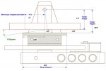
I will call Ernie and have him send me the new double-bearing head, with the undersling set at 4.95".

The next part is to attach my hydraulic pre-rotator. That one has me stumped right now, but I will start a new thread on that.

Alan, the anti-flap brackets have holes drilled on the same plane as the top teeter bolt hole. Thanks for pointing out the possible issue with the anti-flap brackets if they are not on thesame plane. I never thought about that!

I figure that the RFD brackets ought to work if I get RFD teeter towers and a new RFD double-bearing block.

Oh yeah - other news: I replaced my intake manifold with a self-made, TIG-welded aluminum intake based upon the stock VW center mount intake and a carb plate made to fit a Holley Model 1920 single-barrel carb. It works like a DREAM!

I have "factory" carb heat from two exhaust manifold heat risers that heat the intake. Bottom line: max RPM stayed the same, and I have no more condensation on my intake, and it idles like a well-tuned Harley.

It starts on two turns, and after a quick 1500 RPM warm-up for about a minute, it idles smoothly at 650 RPM (no choke) Oh yeah! I also torched and bent my tailwheel spring, giving me additional clearance between the new MATCO 5" tailwheel and my larger, red and white striped rudder.

Tailwheel mod - check!
carb modification - check!
Rotor head - decision made, waiting on order and delivery!

Now it's only to get my pre-rotator operational, and I am in business!

The trick to getting a gyro built, I have found (the HARD way), is that you have to work on something EVERY DAY, no matter how small. A bolt here, a rivet there, a shot of paint over there, and it will build upon itself - but you have to do something every day.

After 2-1/2 years of fiddling and futzing with a nearly completed gyro, I'm finally almost there. I errantly tackled big projects as big projects, instead of taking a bite at a time, and I've been eating my arm off in jealousy and frustration as I look at videos and pictures of you all flying... Life's a cinch, inch by inch...life is hard, yard by yard...

I finally can see light at the end of the tunnel, and a lot of information has become clearer to me now, especially about the mechanics of building a tractor gyro - and that is thanks to YOU ALL. I appreciate the time and effort you have all shown in helping me see the light in some engineering areas I was rusty in. I had a great time over the past two days doing geometry again and figuring out arctans and cosines of angles to figure the teeter angle. I feel I could pass an 8th grade geometry final now!!

Anyhow, I'm feeling pretty positive right now, and hope to get my "Invasion Stripes" up in the air and barnstorming before the end of the year.

Cheers again for all the help - I wouldn't be at this point without all the experience, advice, and words of encouragement.

Sincerely,

Magilla 06 (my National Guard call sign)
 
Top