Focke Achgelis Fa 330

I find it interesting that designers of the FA-330 got blade area correct for the operating conditions of that machine while modern gyroplane designers don’t appear to have the same ability, running blade loading too high and therefore rotor tip speed much higher than necessary. In effect, sending those expensive Rotax horses to the dogfood factory.

Each hp consumed by the rotor requires nearly 3 hp at the propeller.
 
rotor tip speed much higher than necessary
Very interesting observation, Chuck! One possible answer might perhaps be that extruded blades are made in a "one fits all" fashion (well, allmost) because the manufacturing is so expensive that the companies try to cover as wide a scope of aircraft as possible. Does anyone have an information as to whether Ken Wallis' gyros had a lower tip speed? His blades after all were custom made.
 
Last edited:
Yes, Chuck. Modern gyroplane designers certainly have not the same ability as Focke-Achgelis. However they do well to copy Bensen:
The "solidity" σ ratio of FA330 on a seesaw rotor would require too blade mass for low coning and bearable vibrations.
In addition, cumulating high pitch setting and low tip speed of FA 330, the Vne becomes too low (autorotative limit)

Juergen,
The tip speed of Wallis 116 is about 290 mph.
 
Last edited:
Cierva eventually standardized on a blade loading of ~35 lb/ft² as having the best Cl/solidity ratio for forward speed of ~100 mph. That results in a rotor tip speed of ~390 fps (265 mph).

Bensen stayed within the Cierva guidelines but could have benefited from a bit more blade area since open frame gyros don’t need 100 mph forward speed.

The performance of the heavier 2-place gyros would be much improved with more blade area but as JC says, vibration could be a problem with a Bensen rotor system.
 
Chuck, I do not know how Cierva reached this conclusion.
Based on my simulations, it is slightly better to reduce blade chord from 7" to 6" on my 21' , when I take into account the weight gain to permit the same coning. However I do not consider the small reduction in the Reynolds number.
Mainly, the stiffness of my wooden blades would insufficient with 6" .
 
JC, as you know, in the upper speed range, induced drag power becomes very small but rotor profile power increases as the cube of tip speed.

Cierva kept rotor tip speed no higher than necessary, which requires that mu = 0.35 be reached near the upper limit of airspeed.

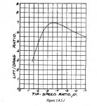
The attached graph was scanned from “Principals of Helicopter Engineering” by Shapiro. It originally came from a NACA report by Wheatley.
 

Attachments

  • Focke Achgelis Fa 330
    mu.jpg
    33.7 KB · Views: 5
That’s correct according to Shapiro’s bibliography, Juergen. The link doesn’t work for me.
 
JC, as you know, in the upper speed range, induced drag power becomes very small but rotor profile power increases as the cube of tip speed.

Cierva kept rotor tip speed no higher than necessary, which requires that mu = 0.35 be reached near the upper limit of airspeed.

The attached graph was scanned from “Principals of Helicopter Engineering” by Shapiro. It originally came from a NACA report by Wheatley.

Chuck,
Suppose a gyroplane perfectly well suited with constant Lift. The operating point is at the top of the curve L / D.
So, you say lower RRPM giving mu larger gives more drag.
Now, in reference to profile power, you say lower RRPM gives less drag.
I Let you come out of this fun pradoxe.
 
Last edited:
Chuck,

I do recall reading in other various publications and papers that Cierva did settle on the maximum blade loading of 35 lb/sq ft, however I don't recall Cierva settling on a solidity ratio of no less than 0.035 that is commonly espoused by modern gyroplane designers.

In Martin Hollmann's book, FLYING THE GYROPLANE, he reports the following:

Cierva C30
Empty Weight - 1,261 lb
Gross Weight - 1.900 lb
Rotor Diameter - 37 ft
Blade Cord - 11 in
Number of Blades - 3
Solidity Ratio - 0.047
(Blade Load - 37.346 lb/sq ft)

Fa 330
Empty Weight - 180 lb
Gross Weight - 420 lb
Rotor Diameter - 24 ft
(Blade Cord - 11.988 in)
Disk Load - 0.73 lb/sq ft
Number of Blades - 3
solidity Ratio - 0.0795
(Blade Load - 35.964 lb/sq ft)

Hafner Rotachute
Empty Weight - 90 lb
Gross Weight - 290 lb
Rotor Diameter - 15 ft
Blade Cord - 8 in
Number of Blades - 2
Disc Load - 1.64 lb/sq ft
Solidity Ratio - 0.0565
(Blade Load - 28 lb/sq ft)

Bensen B-8M
Empty Weight - 247 lb
Gross Weight - 500 lb
Rotor Diameter - 20 ft
Blade Cord - 7 in
Number of Blades - 2
Solidity Ratio - 0.037
(Blade Load 20 ft dia rotor - 42.856 lb/sq ft)
(Blade Load 23 ft dia rotor - 37.267 lb/sq ft)

HA-2M Sportster
Empty Weight - 630 lb
Gross Weight - 1,100 lb
Rotor Diameter - 28 ft
Blade Cord - 9 in
Number of Blades - 2
Disc Load - 1.79 lb/sq ft
Solidity Ratio - 0.034
(Blade Load - 52.381 lb/sq ft)

McCulloch J2
Empty Weight - 1,000 lb
Gross Weight - 1,500 lb
Rotor Diameter - 26 ft
Blade Cord - 6.74 in
Number of Blades - 3
Disk Load - 2.82 lb/sq ft
Solidity Ratio - 0.0413
(Blade Load - 68.478 lb/sq ft)

Air & Space 18A
Empty Weight - 1,315 lb
Gross Weight - 1,800 lb
Rotor Diameter - 35 ft
Blade Cord - 12.5 in
Number of Blades - 3
Disk Load - 1.87 lb/sq ft
Solidity Ratio - 0.057
(Blade Load - 32.914 lb/sq ft)

Granted, Hollmann had a history of some inaccuracies in his figures, however I think the above list is within the "ballpark" of actual measurements. The blade load measurements in parentheses are based on the above figures and were not provided by Hollmann.

There is merit in using a three blade, fully articulating rotor system with larger and heavier gyroplanes, however we all know that more complexity means more cost.

The reality is we're basically stuck with the relativity inexpensive, 2 blade, semi-rigid, teetering, rotor system, especially if we want a gyroplane to fit within the current Sport Pilot regulations. As a result, we inevitably give up the maximum recommended blade loading of 35 lb/sq ft.

Chuck, I personally would like to see a simple three blade rotor system based on your original design on a number of two place gyroplanes now in existence. Think of the performance gain as a result!

Wayne
 
Last edited:
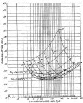
Here’s another chart, JC, from “Aerodynamics of the Helicopter” by Gessow & Myers.

P/L = 0 = autorotation.

Cl = lift coefficient of rotor disc

The plot of profile drag Vs incidence (Θ) shows the effect of tip speed variation.

I’ll be back later but now have an appointment I must keep.
 

Attachments

  • Focke Achgelis Fa 330
    L-D 001.jpg
    82.1 KB · Views: 3
Chuck,
Suppose a gyroplane perfectly well suited with constant Lift. The operating point is at the top of the curve L / D.
So, you say lower RRPM giving mu larger gives more drag.
Now, in reference to profile power, you say lower RRPM gives less drag.
I Let you come out of this fun pradoxe.
JC, the L/D plot from post #26 mainly reflects induced drag vs airspeed. The decrease of L/D beyond μ = 0.35 reflects the increasing stalled area of the rotor disc.


Profile drag vs airspeed rises slowly; the increased profile drag on the advancing side of the rotor disc is greater than the decrease on the retreating side until Mach drag divergence is reached. That occurs at a freestream Mach number less than 1; the local velocity over the blade surface matters most.

I’ve never seen a plot of drag vs tip speed at zero lift but expect it will be higher than the value calculated for drag coefficient taken from wind tunnel airfoil measurements. Centrifugal force acting on the boundary plays a significant role.
 
.Chuck, I personally would like to see a simple three blade rotor system based on your original design on a number of two place gyroplanes now in existence. Think of the performance gain as a result!

Wayne
Wayne, all of the heavier machines could benefit from more rotor blade area. No point in simply torturing the air and burning up those expensive horses.

I’m not sure that the vibration problems of wide chord seesaw rotors can’t be solved; Bell Hueys and Huey Cobras had chords of 18-24 inches but people more familiar with those machines than I say they had quite a thump.

I’ve flown both tilthead 3-blade rotors with zero offset flap hinges and fixed head floating hub rotors on light gyros that didn’t really need more than 2 blades. Drag hinges always require drag dampers and usually dampers on the landing gear.

I didn’t fly the floating hub, hingeless rotor higher than I was prepared to fall until I could run a strain gauge survey on pitch spindles and other root fittings; I had acquired strain gauges for that purpose but lost interest before I got around to it.
 
Last edited:
The decrease of L/D beyond μ = 0.35 reflects the increasing stalled area of the rotor disc.
Exactly Chuck,
And since a decreasing of the solidity ratio σ produces an increase in RRPM, then the A.o.A of the blades keep the same, with the same L/D for the same μ : The shapiro curve (from NACA 515) does not change when we changes σ

rotor profile power increases as the cube of tip speed.
it is OK when the blade surface is the same, for example by choosing a smaller pitchsetting. It is not true when the surface decreases (by choosing a smaller σ)

Profile drag vs airspeed rises slowly; the increased profile drag on the advancing side of the rotor disc is greater than the decrease on the retreating side until Mach drag divergence is reached. That occurs at a freestream Mach number less than 1; the local velocity over the blade surface matters most.
The local velocity over the blade surface not reaches the sound velocity before about Mach 0,7. So far, Cd profile remains unchanged. When σ is reduced, just Reynolds number decreases despite the increase of RRPM.

We had briefly discussed this diagram
Juergen,
With your program, you can easily simulate two same diameter rotors at the same lift, at the same speed forward, with different sigma and check that the drag does not degrade.


Ultimately, reduce σ does not change the drag of a rotor of same diameter and same lift, at the same forward speed.
BUT, by allowing to reduce the weight of the blades, the load decreases now, and the drag of the rotor also.
 
Last edited:
With your program, you can easily simulate two same diameter rotors at the same lift, at the same speed forward, with different sigma and check that the drag does not degrade

I followed your idea JC and the results look like this (flight speed is about 100 mph):

sigma _______ rrpm ______ mu _____ fProp
0.0707_______ 192.2 ______0.338 __ 3785
0.0976_______ 148.0 ______0.445 __ 3685

I have used the resultant propeller force which my program calculates to capture the overall effect and the difference is 2%, so my program indicates that you are right JC. I have used the Reynolds numbers at 0.75 R and the approximation formula for profile drag which is in naca 716, so Re is - approximately - also taken into account.

It should be kept in mind that one of the basic assumptions of the above calculation, which uses naca-716, is that the blade is not stalled anywhere around the disk. If this assumption doesn't hold the whole calculation breaks down. With this in mind the question can perhaps only be settled finally using a strip theory calculation which gives local angles of attack for each blade segment
 
Last edited:
Juergen
My blade elements simulation shows that if the chord is reduced by 50%, while the drag increases by only 11%, or only 5% if we consider the low weight of the blades
Focke Achgelis Fa 330
 
Top