Rotor blades - Airworthiness Directive - Celier - Trendak - Argo

Steve_UK

Active Member
Joined
Oct 15, 2010
Messages
3,887
Location
UK
Aircraft
I'm not a pilot but have been lucky enough to fly in Mi-24 Hind, Mi-2, Mi-17, Lynx HAS3, Gliders, GA
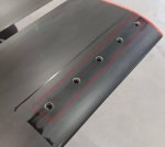
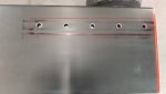
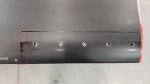
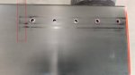
The Polish Civil Aviation Authority ( ULC ) issued an Airworthiness Directive on 25-11-19 regarding the duralumininium blades used on Xenon / Zen1 / Tercel / Argo gyros.

There was a nasty fatal accident in November 2019 near Warsaw killing an instructor and student - I understand one rotor broke off in flight.

The link below will take you to the AD - scroll through it and you will notice that paragraphs alternate between Polish and English.

In summary blades with under 1,000 hours then inspect regularly - blades over 1,000 hours do not fly them.

Please read the document yourself, I may have read it incorrectly.

Link to Airworthiness Directive PDF here


Fly safe
 
Thank you for bringing this to our attention Steve.
 
"Ditto" to you Steve. You do a great service to the goal of safety. Accident review is always a good thing.
 
I knew this pilot. He was a European champion in trikes as well and ran Kompol composites that made the composite parts for Xenon and Trendak. Rest in Peace my friend.
 
It would be helpful to have photos and/or a description of the break -- if only so we'd know what areas to inspect.

We have had a long history of hub/root cracking problems on heavier gyros that employ Bensen's simplified rotor suspension. Igor Bensen was masterful at knowing where, on a small, light gyro, he could eliminate the more complex systems needed in larger rotorcraft. In particular, the Bell "seesaw" rotor system needs an elaborate mast suspension system on heavier craft. We see this on the Huey and Bell 47, but also on helicopters as light as the R-22. Bensen judged that he could go "simple and cheap" on his 250-lb. gyros by using just a limber mast with intentionally minimal bracing. Run big, rigid braces up to the rotorhead of a Bensen and you'll get cracking and even spindle failure.

You can't just "scale up" the simplified Bensen design. 2-place gyros weighing 1200, 1500 or more pounds need a more sophisticated means to allow the center of the rotor to move about relative to the (comparatively massive) airframe. Without this accommodation, the mast, rotor hub and blade roots will take the strain. Some part of this bunch of components will crack sooner or later.

If I were designing a heavy gyro with a teetering rotor, I'd just bite the bullet and weld up a Bell/Robinson style full mast suspension. It's basically a Dynafocal engine mount flipped onto its back.

For those not familiar with the term "Duralumin," it is (or was) an old trademark for 2024 and similar aluminum alloys. I.e. the stuff we all use.
 
Good Morning Doug, I find this topic very interesting. Could you possibly draw what the mast would look like, it sounds like a great idea and not too hard to make.
Thank You
Jay
 
Sounds like a magic mast bushing is what RAF-Canada used for that very reason. Maybe RAF-South Africa still does...
 
The hubbar may have some cone angle?Rotor blades - Airworthiness Directive  - Celier - Trendak - Argo
The directive appears to point to stress points along blade attachment.
 
Images from directive.
 

Attachments

  • Rotor blades - Airworthiness Directive  - Celier - Trendak - Argo
    Fig 1.jpg
    15.6 KB · Views: 116
  • Rotor blades - Airworthiness Directive  - Celier - Trendak - Argo
    Fig 2.jpg
    15.7 KB · Views: 113
  • Rotor blades - Airworthiness Directive  - Celier - Trendak - Argo
    Fig 3.jpg
    16.3 KB · Views: 107
  • Rotor blades - Airworthiness Directive  - Celier - Trendak - Argo
    Fig 4.jpg
    11.8 KB · Views: 106
The picture below appears on the PRA FB page, apparently the broken blade in question;


I would make 3 observations;
1. The blade appears to be in poor condition, surface-wise.
2. The AD is out. The accident report isn't.
3. The extrusion resembles RotorHawk extrusion, but I see no weight insert.

Rotor blades - Airworthiness Directive  - Celier - Trendak - Argo
 
From the photo of the mast of this gyro in post #5, it is obvious why the rotor blade broke.

As Doug points out, Arthur Young’s teetering, underslung rotor requires a flexible mount to run smoothly and avoid strong vibration and ultimate failure.

A soft mount raises the inplane resonant frequency of the rotor/mast combination above the excitation frequency of the periodic aerodynamic input.

I posted an analysis of this behavior on the forum several years ago.
 
Hi All

The first thing I see is they are extruded aluminum. Back when the fleck blades came out there was concern about them.At that time the only alloy that could be extruded for blades was 6063 not 6061 and definitely not 2024 the fleck blades did have a slide in glued in leading edge spar that was 6061-T6 That did add strength to the blades. In the pictures you can definitely see movement from the adaptor used between the blade and the blade grip. At the least the blade plate should have been bonded to the blade. But you would still have a shear point. you can see the shiny spot where the blade adaptor plate ended. There should have been doubler plates bonded to the blades to spread out the bending load at the root of the blade.Helicopter blades weather they were aluminum or composite on most helicopters had a doubler root system like this.
I heard a story from BJ Schramm years ago where a person had put Hughes 269 blades on an early scorpion without any type of doublers on the root of the blade. He told him that there was a shear point at the end of the blade grips and not to fly it. and if he was wait until I am gone.He took BJs advise and did not fly it.. The fleck blades because of not being able to extrude the trailing edge much thinner than .065 were trailing edge heavy there balance point was at around 32% .maybe these blades in the pictures could be overbalanced at the tip. I heard stories from helicopter builder that had the fleck blades on them the collective was so light that it would push up in there hand.

Just my uneducated opinion
 
Here's the Robinson R-22 mast. The tranny case at the bottom has four of the familiar rubber shock mounts (Barry or similar), deployed around the central axis of the mast at some radial distance out from it.

In a gyro, we don't usually have a cast tranny case at the bottom of the mast, but we could create something that functions the same, out of welded 4130.

The engine, cabin, tail-boom structure and other massive components should NOT be mounted on the mast (despite what Bensen did on his featherweight gyros.) This would defeat the purpose of the flexible mount arrangement. (The idea is to keep the whole sprung assembly light; adding mass can get us back into the world of rhythmically bending the blades, hub or mast.) These big masses should instead be mounted to the airframe, which in turn carries the fittings that pick up the bolts from the rubber mounts. In effect, we're treating the mast assembly the same way we treat an engine -- placing it on soft rubber springs so that it can move about relative to the airframe..

Care is necessary in laying out the controls and prerotator, so that movement of the mast assembly on the mounts doesn't load up the pushrods, bearings, shaft and related parts. Putting the same idea another way, these auxiliary connections to the mast must not constrain the mast assembly from moving freely on its mounts.
 

Attachments

  • 20191204114318866.pdf
    128.4 KB · Views: 111
If this Mount was placed at the top of the mast instead of the bottom, would it have the same effect
 
The rotor system's hub bar is also very stiff. Torsional bending in flight is all concentrated on the blade just past the attachment plates with little help from the hub bar. Making the hub bar longer and single piece 6061 would help
 
Inplane rigidity of the rotor is the second part of keeping the inplane resonance of the rotor above the aerodynamic excitation frequency.

The drag struts on Joe Pires’ Aviomania rotor are for that purpose.

More information can be found by looking up “Birth of the Bell Helicopter” part 3 on YouTube. The Bell engineers referred to their rotor stiffening device to avoid 2/rev resonance as the “Swedish Yoke.”
 
Is it possible to design a mast like the detachable ones in the AR1 and TAG, where some dampening can be provided at the detachable joints? The bottom portion of the mast is rigid and attached to the main frame, the top portion of the mast could be fastened with Barry type bushings and could absorb some of the vibrations perhaps. Just my thoughts.
 
Is it possible to design a mast like the detachable ones in the AR1 and TAG, where some dampening can be provided at the detachable joints? The bottom portion of the mast is rigid and attached to the main frame, the top portion of the mast could be fastened with Barry type bushings and could absorb some of the vibrations perhaps. Just my thoughts.
That is what is being designed into the folding mast of my build. Sport Copter and I believe RAF (perhaps others) use an elastomeric bushing at the hinge bolt that provides flexibility. This makes sense for damping the fore/aft vibrations, but with the standard side-plate arrangement of typical folding masts, I'm not sure yet how they accomplish side-to-side damping.

Sorry to divert the thread further. May start a new one on the subject.
 
Top