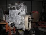
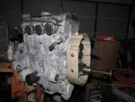
Anything new on Yamaha conversions?

In case the link does not work for everybody , I stole this from the guys at the helicopter forum. They are a pretty good bunch and probably won't mind. It is a note from the belt manufacturer. Hopefully it provides some useful info here.

From the pictures you provided the failure to belt was almost certainly caused by a “crimp” in the tensile cords. This mode of failure is characterized by the uniform break line which extends across the entire width of the belt. The causes of a “crimp” failure are as follows:

Mishandling of the belt: A mishandled belt in which the handler bends the belt to a smaller radius then the recommended minimum pulley radius will damage the tensile cords across the width where the belt was bent, weakening the belt strength and ultimately resulting in tensile cord failure. This is a common problem because it’s very easy to mishandle a belt without awareness of any wrong doing. All it takes is one small bend to damage the tensile cords and promote instantaneous failure. The best way to avoid this would be to leave the belt in the box it came in until it’s ready to be installed. This will reduce the risk of anybody getting their hands on the belt who does not know the proper way to handle it.

Sub-minimal sprocket diameter: This is the same affect as mishandling the belt. If the belt is bent to a smaller then recommended radius the tensile member can be damaged resulting in tensile cord failure.

Inadequate belt installation tension: If a belt is undertensioned enough to make the belt start ratcheting over the sprocket teeth, the movement of the belt climbing over the teeth then quickly sitting down in the adjacent groove can cause an instantaneous crimp in the belt, resulting in tensile cord failure.

Entry of foreign objects within the belt drive: This will cause the same affect as inadequate belt installation tension. If a foreign object gets stuck between the pulley groove and belt, it can cause the belt to jump up and down very fast, resulting in an instantaneous crimp and tensile cord failure


I noticed from the pictures you sent me there is a small nick running down the center of the belt (see attached picture). It’s possible that the mark was caused by a foreign object which was caught between the belt and sprocket, causing the belt to jump up and crimp, as described above. If this was not the case, the belt was still most certainly caused from crimp failure.
 
Gyro Jockey Gerg

Just back from a road trip. No offense taken on your commentaries to my posts. As I said, there's no need to reinvent the wheel, but you do need to get the right info. A couple pieces of useful belt drive info that apply to toothed HTD type belts:

*There is no dampening provided whatsoever by a toothed belt in a drive system. Can't over stress this enough.

*Idler could be developed to provide some form of dampening, but it would quickly enter into a resonance with the torsional pulses and either the belt would follow suite or the idler would suffer damage very quickly. Suburu uses an automatically hydraulically dampened tensioner for their cam drive belts.

*Yes, idler on the inside of the belt is better, but idler on the outside is used in just as many applications. Almost all import cam belts for example. There is a little more fatigue of the belt over time since it flexes both ways in its travel around the sprockets, but no significant amount.

* Idler on the outside of the belt allows more teeth wrap on the bottom sprocket. Teeth in contact is most important factor in HP transmission and reliability.

* Idler diameter is another important factor and should be as large as the smallest sprocket in the drive system- hence the need to work with something custom as all aftermarket automotive cam tensioners are too small in diameter. It also keeps the high RPM limit of the idler bearings at a reasonable value.

* Deep drive ratios require much larger upper pulleys while keeping the small drive pulley as large as possible. This ends up costing way more money and also creates a larger "V" between the two pulleys, thereby decreasing teeth in contact on the bottom sprocket. Ratios above 2.5 to 1 rapidly become too heavy, to big, too costly.

* High RPM limit is a factor on the engine you are looking at. Take time to look at the tables for HTD belt RPM limits. We designed a HTD belt driven supercharger that ran 60,000 RPM on the input shaft to the compresser, however, the power transmitted was only about 2HP with a very tiny toothed belt. Resonance and belt float were still problems.

Your earlier idea of recycling the stock snowmobile clutch is looking better all the time.

* Keeping the weight of the stock clutch/flywheel on the crank is a real plus to help dampen torsionals.

*Clutch disengagement at low RPM can let the engine idle without torsional shake. Just lock the upper drive sprocket so it can't upshift and you will have something functional like the centrifical clutch/ fixed ratio gearbox that Racer is using.

Hope this is of some use.

Fly Safe!

Jeron Smith
Raven ReDrives Inc.
 
Gyro Jockey Gerg

Just back from a road trip. WELCOME BACK! No offense taken on your commentaries to my posts. GLAD TO SEE YOU ARE THICK-SKINNED. MY BEST FRIENDS ARE THE ONES WHO'VE MOST LIKELY SUFFERED MY ILL TEMPER AND GOTTEN OVER IT. As I said, there's no need to reinvent the wheel, but you do need to get the right info. A couple pieces of useful belt drive info that apply to toothed HTD type belts:

*There is no dampening provided whatsoever by a toothed belt in a drive system. Can't over stress this enough. CHECK.

*Idler could be developed to provide some form of dampening, but it would quickly enter into a resonance with the torsional pulses and either the belt would follow suite or the idler would suffer damage very quickly. Suburu uses an automatically hydraulically dampened tensioner for their cam drive belts. THIS COULD BE PURE GOLD.

*Yes, idler on the inside of the belt is better, but idler on the outside is used in just as many applications. Almost all import cam belts for example. There is a little more fatigue of the belt over time since it flexes both ways in its travel around the sprockets, but no significant amount. DEFLECTION WILL BE KEPT VERY SMALL NO MATTER WHAT, REGARDLESS.

* Idler on the outside of the belt allows more teeth wrap on the bottom sprocket. Teeth in contact is most important factor in HP transmission and reliability. CHECK

* Idler diameter is another important factor and should be as large as the smallest sprocket in the drive system- hence the need to work with something custom as all aftermarket automotive cam tensioners are too small in diameter. It also keeps the high RPM limit of the idler bearings at a reasonable value. CHECK.

* Deep drive ratios require much larger upper pulleys while keeping the small drive pulley as large as possible. This ends up costing way more money and also creates a larger "V" between the two pulleys, thereby decreasing teeth in contact on the bottom sprocket. Ratios above 2.5 to 1 rapidly become too heavy, to big, too costly. THIS APPLICATION REQUIRES 3:1 BARE MINIMUM, 3.8:1 GETS TO REDLINE.

* High RPM limit is a factor on the engine you are looking at. Take time to look at the tables for HTD belt RPM limits. We designed a HTD belt driven supercharger that ran 60,000 RPM on the input shaft to the compresser, however, the power transmitted was only about 2HP with a very tiny toothed belt. Resonance and belt float were still problems. I THOUGHT THE ONLY THING AVAILBLE FROM GATES WAS A 25 OR 30mm BELTS, BUT MY PEER HAS A PRODUCT CODE GIVEN TO HIM FROM GATES THAT APPARENTLY IS RATED FOR THE RPM AND HP IN A 60mm X 8mm Pitch.

Your earlier idea of recycling the stock snowmobile clutch is looking better all the time. AT LEAST IT WON'T COST MUCH TO TRY IT OUT.

* Keeping the weight of the stock clutch/flywheel on the crank is a real plus to help dampen torsionals. CHECK

*Clutch disengagement at low RPM can let the engine idle without torsional shake. Just lock the upper drive sprocket so it can't upshift and you will have something functional like the centrifical clutch/ fixed ratio gearbox that Racer is using. ANOTHER THREAD POSTER I SPOKE WITH HAS DONE JUST THAT, AND INDICATED IT WORKS FINE BUT THERE IS EXCESSIVE BELT WEAR. I CAN'T BE SURE WHAT IS CAUSING THAT, FOR ALL WE KNOW IT COULD BE AN ALIGNMENT ISSUE OR SOMETHING ELSE. HARD TO TELL FROM JUST A SHORT, TYPED MESSAGE. AS I MENTIONED BEFORE, A PROP RPM INDICATOR WOULD REALLY HELP, ESPECIALLY IN THE DEVELOPMENT AND TESTING STAGES.

Jerod, My comments in caps, inserted above.
 
anyone else on here building 4 cyclinder yamaha project ,started on mine today .started machining clutch first if you are doing the same contact me mark miller would like to compare notes
 
Hey, Mark, can you meet us in Wauchula, FL for the Bensen Days Fly-in? I'll be there, I think that Ernie will bring his Yamaha conversion. He did such a nice job on his 4-cyclinder yama, you really should see it first hand. I took gobs of photos, and I now realize I need many more.
 
yammy hammer

yammy hammer

i had a visit with erine several months ago,nice guy.i just got side tracked on my project.i machined my side drive plate on bridgeport mill,my cnc machine is down should be fixed in week and ill be back on it. whats the date on flyin. mabe ill fly my ultrlight thanks mark
 
Goodness, how time flies...along with me and the other gyro pilots around here. I can't believe it has been fully 6 months since I had anything to say about this project.

I realized very recently that the Warp Drive prop that I got with the Air Command I bought from Ora Cook is a high-HP prop, so I can use it on this build if I use a conventional gear redrive or the other solution I spoke of previously in this thread. I also found out from Neil Heintz, when we spoke at Bensen Days 2011, that his brilliant solution to the clutch problem on Yamaha redrives, to get rid of bad vibrations during warm up at low engine rpms, was to employ the sprag clutch system commonly found on Arrow engine redrives. This is actually most likely an excellent solution to ELIMINATE prop-to-engine pulsations, the vexing demon of redrive demise.

I just figured out this week that the drive shaft on the Yamaha 4-cyl is of the same exact dimensions as the crankshaft of the Arrow engines.

You see where I am going with this discussion, no doubt. The sprag-clutched, Arrow redrive can be geared to 1:3.01. That would be perfect for this engine. I have a 1:2.77, which means when the Yamaha is turning 8000 rpms at the output shaft, the engine would be revving at 9520, just a smidgeon shy of peak HP and probably right at the sweet spot of peak torque, and the prop would be turning 2888, just a tad over peak prop performance hump. Not bad, I think I may have all the ingredients in my shop to make this engine conversion work, with very minimal adapter and mounting hardware needing to be fabricated.

I started tearing down the gearbox on the first Arrow I have, it is only 1:2.58, and not my first choice for the Yamaha conversion, but it will be a good mock-up so I dont' have to mess around with the Air Command I am now flying these days until the time comes for the actual installation later on, after all the brackets and adapter plates are built and ready.
 
Last edited:
Gerg, it occured to me while I skimmed over this last page of post's, my first visit,
that if you have deep enough pockets to complete this engine experiment that will carry two souls, then you could afford a used Rotax 914 and fly safe. Am I wrong?
My Dad had a saying, "Don't bite off more than you can chew".

Well, I have $3000 into the Yamaha conversion so far. Everything else is in the shop, not originally purchased for this project, so "free" in a way. While we're comparing, price aside since the used Rotax 914 - if you can even find one - couldn't come close to $3000, how much does the 914 weigh, and what HP does it produce?

I have been told by several reliable sources that I can expect 150 hp out of this engine. It weighs 125 lbs.
 
Last edited:
oh...DOH! I fell hook, loin and sinka, dint i?
 
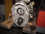
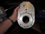
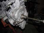
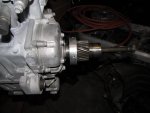
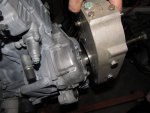
OK, pictures for everyone This is so exciting. I tried many times, with many different solutions to get the drive gear off the shaft. The spacer washer used on the shaft-end bolt came in handy to keep the gear puller tool bolt tip from slipping off to the side. Then I cranked the crap outta the puller, hit it with a ball peen hammer, and the whole dam thing flew across the garage about 10 feet when it all let go at once! Glad I wasn't standing in the way.

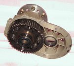
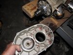
In the first photo is the outer cover with the driven gear, the sprag clutch housing, attached to the prop hub. It's fun to show my wife how it rotates in only one direction freely, in the other it is locked up.

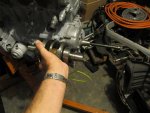
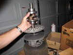
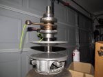
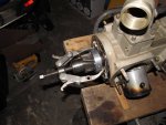
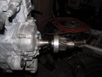
Next is the back housing, which only carries the driven shaft bearing. Pic #3 shows the Arrow 2-cyl crankshaft next to the Yamaha shaft end for comparison. 4, the Arrow crank is inserted into the Yamaha CVT drive sheave. Such a perfect fit that after I inserted it and let it sit for a few minutes, I had to coerce it free.\

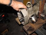
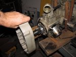
5, 6,7,8 removing the rear gear box housing. It pops right off.
 

Attachments

  • IMG_0591.jpg
    IMG_0591.jpg
    132.5 KB · Views: 0
  • IMG_0595.jpg
    IMG_0595.jpg
    126.8 KB · Views: 0
  • IMG_0599.jpg
    IMG_0599.jpg
    127.7 KB · Views: 0
  • img_0590.jpg
    img_0590.jpg
    76 KB · Views: 0
  • IMG_0598.jpg
    IMG_0598.jpg
    127 KB · Views: 0
  • IMG_0600.jpg
    IMG_0600.jpg
    132.4 KB · Views: 0
  • IMG_0601.jpg
    IMG_0601.jpg
    132.6 KB · Views: 0
  • IMG_0602.jpg
    IMG_0602.jpg
    127.9 KB · Views: 0
Last edited:
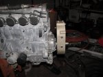
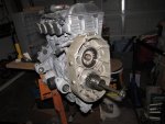
Sliding the drive gear onto the Yamaha output shaft, then the rear housing on, to measure gap from the Yamaha output shaft bearing bolts for the adapter plate thickness determination. !/2" adapter plate material will work well. Need to seal it on the rear (engine) plane with an O Ring, and on the front (gearbox) face with a gasket.

That long bolt in the output shaft is the OEM attachment hardware for the snowmobile CVT sheave.
 

Attachments

  • IMG_0605.jpg
    IMG_0605.jpg
    126.7 KB · Views: 1
  • IMG_0606.jpg
    IMG_0606.jpg
    123.1 KB · Views: 1
  • IMG_0604.jpg
    IMG_0604.jpg
    132.7 KB · Views: 1
  • IMG_0611.jpg
    IMG_0611.jpg
    124.8 KB · Views: 1
  • IMG_0612.jpg
    IMG_0612.jpg
    123.1 KB · Views: 1
  • IMG_0607.jpg
    IMG_0607.jpg
    131.4 KB · Views: 1
  • IMG_0613.jpg
    IMG_0613.jpg
    126.3 KB · Views: 1
So all that's left to decide is should the redrive be mounted with PTO shaft on top or bottom? Any thoughts???
 

Attachments

  • IMG_0614.jpg
    IMG_0614.jpg
    129.5 KB · Views: 0
  • IMG_0615.jpg
    IMG_0615.jpg
    126.5 KB · Views: 0
  • IMG_0616.jpg
    IMG_0616.jpg
    128.2 KB · Views: 0
Last edited:
Greg, to bad it's such a crappy day...I'm just north of atlanta heading your way. would'nt mind seeing the ol tandem again :~)
 
I hate to see an Arrow go down, but I guess it is inevitable.
The only problems I had with my Arrows was the sprag. I hope you have better luck.
I have read somewhere, that if you only use about half of the recommended amount of lube, your sprag problems are eliminated. I didn't hear of this till after I got rid of them.
Is that engine side cover gonna need milling for a suitable mating surface?
Is the rotation the same?
As to shaft up, down, It is reversable by design, so just get the mounting plate built with the proper clearances and you can determine later how it should go.
I think if you can work out the kinks, you will have a winner.
 
Top