New Hornet(s) in the works!

Dennis, good to see you back. Was interested to see when you would start on her again but you did say you were busy.

Congratulations on the good woman, support in this direction is a huge plus. Look forward to seeing how she works out... the gyro that is.
 
robo_nipsy : And i thought I was bad about making chips.....geeeeees

I can't wait to see the tall tail when your done.....
 
Progress Continues.....

Progress Continues.....

Thanks for the compliments guys!

Well, we have made some more progress!

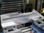
Tom Patterson stopped by yesterday to assist in the drilling of the rivet holes in the spars for the tail section.
It almost took longer to lay out all the drilling positions and make the fixtures than it did to design the parts themselves, but I think it was worth it.
The fixture holds all the parts at the correct angle so that the rivet hole is perpendicular to the surface. I refer to this fixture as the "Hornet constellation" :)

As I mentioned, I am having the 24 Ga aluminum skin laser cut with all of the rivet holes included. I'm getting excited to see how everything lines up.
Getting the drawings ready for laser cutting was a task in itself. I send out a lot of machine parts weekly for this same thing....shelf brackets, drip trays, belt guards, etc... these are usually pretty simple, (boxy, straight bends).. I can export from the CAD software, and they can take my files and load it into the laser and cut..no problem.

For this (somewhat) airfoil shape however, it gets a little trickier....
When you drill a round hole through a curved piece of sheet metal, and then lay it out into its flat pattern,you no longer have a round hole. The material gets compressed on one side and stretched on the other. In the cad file, you now have a series of many, many small line segments representing the perimeter of the hole (called a spline).
Now, most software for these lasers and such now days can pick up on this and still cut the hole (or a very close representation of it) no problem. But some times, there many be a small glitch in one of these splines (or a large group of them) and cause the laser to just ignore them all together. What you end up with is a part with only half as many holes in it as you wanted!

So, for these parts, I did not want to take any chances...I went and replaced every one of these splines with a true 1/8" circle. That took some time!!

I don't know if the laser-cut parts will be ready this Wednesday or next. (I am there every week) But, I have asked if I could be present during the cutting to possibly get some pictures or video....It would be some nice documentation to go along with my build log...(and to share here)

I have just a couple more parts to machine for the tail before we will be ready for assembly. I'm hoping we will be ready for our "riveting party" within a couple weeks.

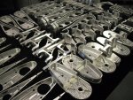
I've attached a picture of some more machined components for the tails...Remember now, the parts shown are for at least 3 full assemblies. A full completed tail assembly should come in at just over 14 pounds.
I know I showed the spars before, but I thought they looked a lot cooler now with the rivet holes included.
I also attached a couple videos showing Tom and myself drilling the spars yesterday. (I hope........this is my first attempt at posting a video)

This is fun!
Denis

YouTube - Rivet Hole Drilling_Front Vid.AVI
YouTube - Rivet Hole Drilling_Rear Vid.AVI
 

Attachments

  • New Hornet(s) in the works!
    Empannage_Machine Parts 2_18_11.jpg
    140 KB · Views: 2
  • New Hornet(s) in the works!
    DSCF4141.jpg
    134.2 KB · Views: 2
robo_nipsy : Program the machine and it takes off.... Great work on your part....cutting and drilling.....;)
 
For this (somewhat) airfoil shape however....

Have you done any testing of the airfoil section for it's aerodynamic properties or are you just hoping for the best? Just because it looks streamlined doesn't mean it will be if you have flow separation at an early chord percentage.

.
 
Fascinating to watch that Dennis. That is seriously professional compared to our Hornet build.

Glad its coming on, look forward to seeing the finished item.
 
Thanks

Thanks

Kai,
Thanks...It feels weird being called a pro when I am a total newbie at this sport!

Resasi,
I am fortunate to have access to nice tools...It seems that everybody here puts forth their best craftsmanship with the tools that are available to them...It's all that can be asked of anybody.

Dog,
CNC is nice...Especially when you get into production work, you can knock out a lot of parts in a hurry and with great repeatability.
However!!!...A lot of people seem to think that the CNC takes all of the work out of everything...Not so...
For some of the small jobs, like most of us are doing here. a manual machine is just fine. If I just needed to face off the end of a part and was having a race with someone on a manual mill, they would have their part complete while I was still entering tool offsets, speeds & feeds, cut direction, coolant commands, rapid planes...Etc....
Yes, the cool factor is there, but when it comes to making a good quality part, that is dependent on the operator...Not the machine.
It looks like you are gaining a lot of skill in a hurry! Good job!

Alan,
Good question.
No I have not performed any analysis on the profile. I wanted to make sure I was open about this and that is why I included the "(somewhat) airfoil shape).
You are right I am "hoping for the best". It sure seems that the profile that I have is a heck of a lot better than just throwing a hunk of lumber on the back for a tail...But you are right, assumptions like this can end up in death.
If I was to provide the profile (in any format) is there anyone out there who could perform some computer analysis on it for me?? It would be much appreciated.
I am already into this design pretty deep, and so I will continue the build with the assumption that this will be as good as if not better that a simple plywood tail...But before this thing sees any flight time, I should get some verification.
I thought of mounting this on a tall mast in the back of my pick up and having someone drive me down a back road (when the weather gets warmer) and try a little smoke test around the airfoil...Would this work?

Does anyone have any ideas for making a smoke generator??
I have some very small diameter brass tube that could be used for the "wick"...Could I just build a simple PVC chamber that I could attach the brass tube to and throw a smoke bomb in??? Would the burning of the smoke bomb create enough pressure to push the smoke out the wick? Too much? Or would it extinguish itself as soon as the 02 ran out?
Hmm.. Could be fun to experiment with regardless...

Later
d
 
Getting the air to divide and flow smoothly around the leading edge is the easy part, putting it back together without separation and drag is another thing and this is were the airfoil shape aft of the maximum thickness is important.

While smoke would be nice yarn or string used as tufts would also work well and with less effort. I would definitely suggest you do some testing both in smooth air and prop blast.

.
 
Great idea Alan!
Thank you.
As as soon as I get one of these assembled and the weather warms up I will perform some flow tests. I will definitely post pictures and test results as I progress.
d
 
Alan,
No, not as of yet. I could easily make something that would extend forward off of the control horn at the bottom and wrap around to the front of the stationary leading edge to achieve this...
Do you think it will be necessary? What are the potential negative effects if I don't? Flutter?
Any recommendations?

Dog,
I used needle bearings in mine... This however has raised much discussion & debate within my Chapter 17 group. Especially for the main teeter bolt when attaching the rotor blades. Not sure if any potential benefits outweigh the negatives...I still might go back to some PTFE lined sleeve bearing instead..
Yes, I built all my own components for this but, let me reiterate that I am new to all this. I will have to decline to comment on anything to do with critical parts such as the rotor head.
I don't want anyone to take the decisions that I have made on my build to be taken as proven recommendations.
d
 
Denis,

If your tails center of gravity is behind the hinge line you can get a dynamic yaw instability that in some cases can be severe enough to cause loss of the aircraft.

Two cases in point deal with my friends gyros.

At one point he had a local fiberglass guru fabricate an over sized tall tail for his ship. This tail used a solid foam core and was fiberglassed which resulted in the CG being quite behind the hinge line, even with pieces of steel re-bar embedded in the leading edge. The result of this CG problem lead to a dynamic yaw instability that would grow worse and worse unless the pilot kept significant and fatiguing pressure on the rudder pedals. The instability was so bad that if a rudder cable had broken in-flight there would be no way to get the ship down successfully, and even with pressure it still had a tail wag that shows up in the videos I made of his flights.

In the second case another gyro and anther tail, this time not a tall tail but one that still had the CG behind the hinge line despite using a lead weight on a counter balance tube. Although the instability was not as bad as the composite tall tail it still was unstable and required a trim tab on the trailing edge to tame it down to acceptable levels.

If I were designing a tail I would design for 100% counterbalance about the hinge line or use an anti-servo tab like on the Dominator tails. For symmetrical section airfoils the hinge line should also be located about 33% of chord.


As for needle bearings, that's fine if properly done.

.
 
Hi all,
Dirtydog had previously asked me about specifying a brass/ bronze alloy for some bushings...although I declined (I don't know why, maybe I'm too worried about liability or getting slammed :) ) anyhow, I do feel I have a little tip when it comes to machining these...

A word of caution, when machining any red metals (Brass, copper, bronze)...these materials can be very "grabby".. If you are enlarging a drilled hole for example, if you don't have a good solid hold of the drill bit (as in the tail stock of your lathe), and you try to feed too fast, the drill can grab and try to screw itself in just like driving a screw into a piece of wood. But, the pitch of the helix on a twist drill is a lot steeper than that of a wood screw, so it tries to do this in one heck of a hurry!

Sometimes the best is to ever-so-slightly flatten the cutting edge of the drill bit. A neutral rake angle works pretty good.
By rake angle, I don't mean the 118' point, but the angle of the cutting edge in relation to being perpendicular to the work piece.
Buttering your bread would be a good example of a negative rake angle. (the knife is forced up and away from the bread) When whittling a piece of wood, the blade is normally held at a very positive angle (and hopefully away from your body :)) to get the blade to travel downward into the wood. A bulldozer moving earth would be a neutral rake angle... Blade perpendicular to the ground.
Drill the hole undersized, and then ream to your final dimension.
Hope this helps,
Denis
 
Last edited:
If not needle the current practice for bearings is Garlock DU bushings (steel backing,sintered porous bronze, PTFE layer) along with inserts which are designed so the pivot bolts are completely isolated from experiencing any movement or wear.

.
 
Thank all for the input.
 
Alan,
Thank you very much for your input. Very interesting.
I will be sure to make allowances for attachment points for an anti-servo tab and/or counterbalance in the design should they be deemed necessary. Now is the time, before I have everything riveted together!
Thanks again!
d
 
Lasers = Cool!

Lasers = Cool!

Hi all!
As promised, I got some video of the tail skins being laser cut last night!
It is short because it was very difficult to get a good angle that showed a lot of the cutting, but yet did not get horrible glare off of the guard door.
My camera kept trying to focus on the guarding, and not on the laser head.
At one point, the operator even shut off the lights in the shop for me to cut down on the glare....The guys in the back of the shop were yelling trying to figure out what was going on :)...Didn't help much though...
Short clip, but it shows the speed and precision of these machines...
Later
d

YouTube - Hornet Tail Cutting
 
Top