New Hornet(s) in the works!

Denis,

One little piece of information that you can file away for later.

The yaw instability, if present, is an interaction of airframe and tail and it's unlikely you will see it while the gyro is sitting on the ground while doing a thrust test, the landing gear prevents free movement of the fuselage.

I had suspected the composite tail on my friends gyro would give problems so even before it's first test flight we did a full power thrust test to see if the tail would give problems, everything checked out ok on the ground, but in the air was another matter.

.

Alan, are you referring to the Dragonfly gyro T tail regarding the instability. I'm building a Dragonfly clone and plan to copy the tail. Would appreciate any advise on what you would change if done again. Thanks, Mike.
 
Alan, are you referring to the Dragonfly gyro T tail regarding the instability. I'm building a Dragonfly clone and plan to copy the tail. Would appreciate any advise on what you would change if done again. Thanks, Mike.

Yes, one of the gyros I refer to was Dragonfly but I hate thread hijackers so I will defer commenting here.

.
 
Progress...

Progress...

Hi all!
Many early mornings and late nights have been spent trying to get all the details finished up so that we would be ready to start assembly on the Hornet tails.
There were many rivet holes to finish, and spacers and stuff..
Attached is a video of some detail machining of the angled spars that are located on the inboard edges of the HS and on the top of the rudder.
These are mounted 40 degrees to the normal direction of the "airfoil" shape. So, in order to get the aluminum skin to lay on this surface correctly, I had to machine somewhat of a 3d contour around the perimeter of these.
You will see that the top edge is rather thin and delicate...I really had to slow down going around this corner so that the end mill did not grab and bend the spar.
I then programed another .002" finish cut to make it all pretty-like.
d

YouTube - Spar Bevel Machining
 
Tail Assembly Day!!!

Tail Assembly Day!!!

Howdy,
Well finally yesterday, the day had arrived when all the parts were ready to begin assembly on the Hornet tail(s)!

Tom and Brent showed up to the shop yesterday morning.
Tom brought burgers to throw on the grill, and Brent showed up with a wooden crate containing my brand new Dragon wings!! Oh my are they pretty!

I had the assembly fixture complete, and all the tail parts mostly ready to go.

We were trying to calculate how much time we had and how much we were going to be able to accomplish in one day....Could we possible get everything assembled and roughly 2500 rivets installed in one day to complete the 3 tails that we were building??

Not so...

After a long day, we were barely able to finish up just Brent's tail alone. Still 2 to go.
It was a lot of fun and overall, we were very happy with the results and our accomplishments for the day.

I invested quite a bit of time into building an assembly jig for applying the aluminum skin to the spars. I made brackets that would hold all of the spars in alignment for the different parts of the tail.

2 rollers mounted on a set of threaded rods, connected via a roller chain were built to provide the wrapping motion of the skin around the spars.
As I say, a lot of time was invested upfront in making all the fixtures, but it paid off very well! The process went wonderfully!! All the rivet holes lined up! We had to open up most of the holes with a .128" drill due to the over-sized rivets, but it was only a very small amount of material removed! I was very pleased!

The total tail ended up weighing in at about 1 pound heavier than what the computer said it would be...Probably some slight variations in the alum gauge thickness and what-not.. (also the weight of some bolts and rivets)
I am very happy with the results!

The assembled parts are very rigid! We attempted to twist and bend the leading edge of the Vertical stab....It would not budge at all!
It is amazing how some flimsy pieces of sheet aluminum, when formed and assembled, can result in such a light and rigid structure!

The inspiration level to get the rest of these machines finished has never been higher. This is so much fun seeing it all come together.

I can't wait to get the other 2 tails assembled and the get them mounted to the frames.

Cheers!
Denis

YouTube - Hornet Tail Assy 4-2-2011.wmv
 
Wow ! that looks Great! You should make 4 instead of 3, I'd sure like to have one myself!! What did it end up weighing? What are the dimensions?
 
robo_nipsy : Nice machine to roll it into place.
 
Hi Denis

Haven't seen anyone ask about that bending machine, so I will. What make is it and where did you get it.

Tony
 
Awesome video. Thank you for sharing. That roller is way too cool. Looking good Denis!
 
Pete,
You really have a gift with words!! That one really made me smile!! Thanks!

Jazzen,
In the video, I show the scale reading 13.8 pounds. This includes everything except the horizontal stab mounting tube which will be a piece of 1 1/2" Dia x 1/8" wall aluminum tube x 48" long. The 'puter tells me that this will weigh an additional 2.53 pounds.
The tail measures 56 5/8" tall. The HS Spans 48", and the "airfoil" shape is 16" from the front tip to the trailing edge.

Chris,
I appreciate the comment!

Tony,
I guess you could say it is a Robo-nipsy brand!!
This is all part of the assembly fixture that I mentioned.
The frame is made out of aluminum extrusion. This happens to be 80/20 brand...I use this material all the time for my machine guarding, so I happen to have a bunch in stock.
The rollers are simply 2" EMT conduit that I got at Home Depot. I made some plugs for the ends of these, a couple end blocks tapped for the 1/2"-13 threaded rods, some sprockets and roller chain, and some more posts made from the same extrusion and some plates to hold the spars at the correct position, and there you have it.

Chopper,
Thank you! I've been watching your build progress as well. Very nice!

Denis
 
Thank you Denis :) I love watching neat stuff like what you are doing. I find it that I can always learn from them and time to time get a great idea from others :) I am the first to admit that!!! :)
 
I've been a bad forum member!

I've been a bad forum member!

Hey all!
Yes, I have been a bad forum member...I have not been keeping everyone posted as to my progress...
But, the good news is that there has been some progress!! Actually, one heck of a lot!
The last 10 months since my last post have been busier than ever...What else is new... But, I do still find time to work on the Hornet...
My time is always limited, so when some spare time, I have to make a choice on how to spend that time...Do I sit down and write on the forum about what I have done, or do I head out to the shop and actually make some more parts...Well, you know....

It's really exciting, because now I have the machine to a point where I am certain that I will have it ready to start some training this coming season!!!! :peace:

So....Where to begin...
I decided that I want to keep the sequence of my build thread progressing at reasonable pace...
What I am going to do is start posting updates on at least a weekly basis... I did take pictures along the way, but some pictures I post will be more recent. So, if you see something in the background that I haven't shown yet, that is why...
This is also going to be my first attempt of using Photobucket to link the pictures...Let's see how it turns out..

There are MANY parts that I have machined over and over.......I know...I would have been up an flying years ago if I wasn't so anal!

Here is one of my first modifications....
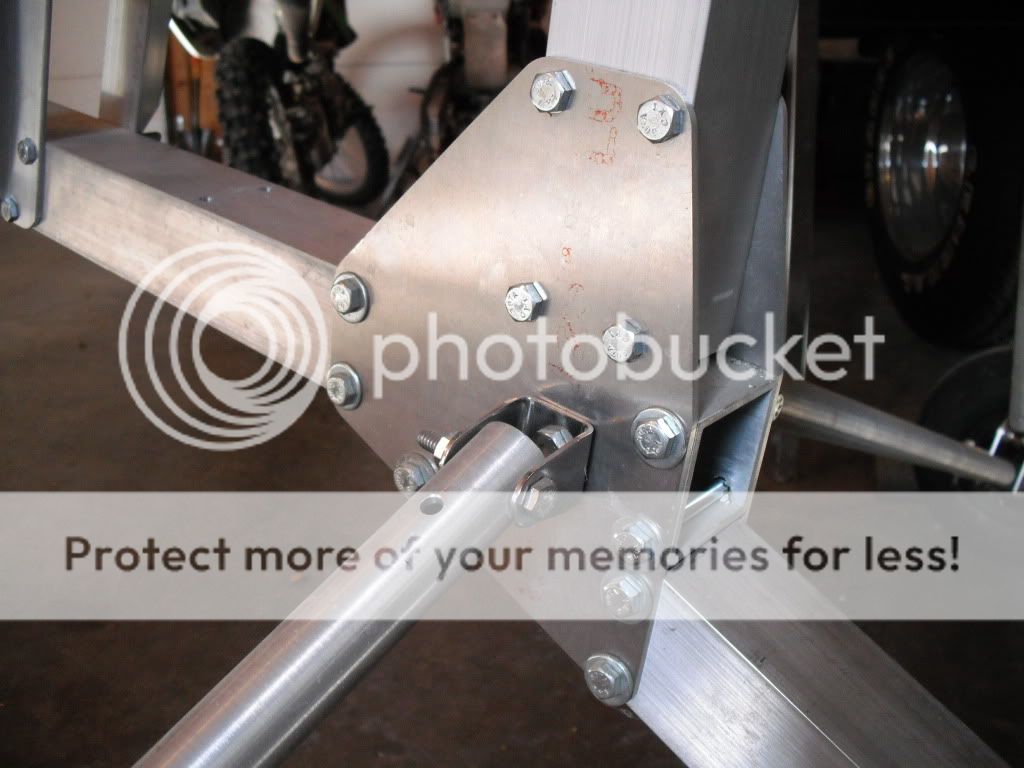
The original plans called for a single hole shackle for mounting the axle strut to the bottom cluster plates as shown.

New Hornet(s) in the works!


I felt this design needed some help, especially if one was going to add some wheel brakes to the design....There is no way that this single bolt would hold any rotational torque.

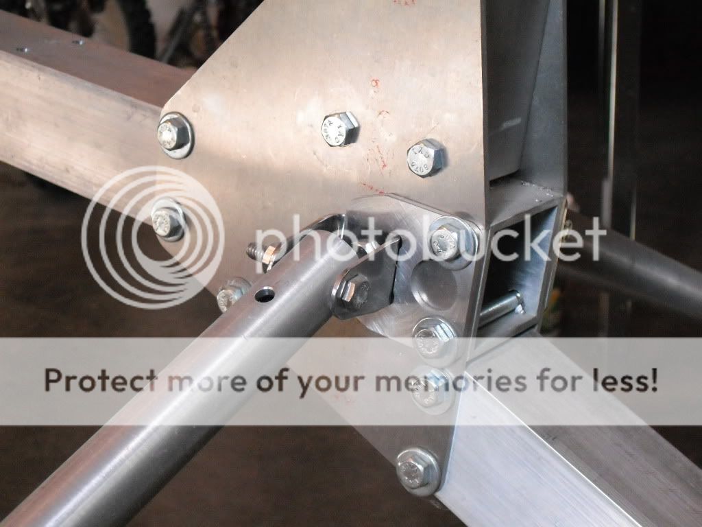
My first "Bandaid" that I applied was to add a C shaped clevis tab around this shackle and pin it to some other bolts in the cluster plates...

New Hornet(s) in the works!


This helped, but still not an elegant solution.
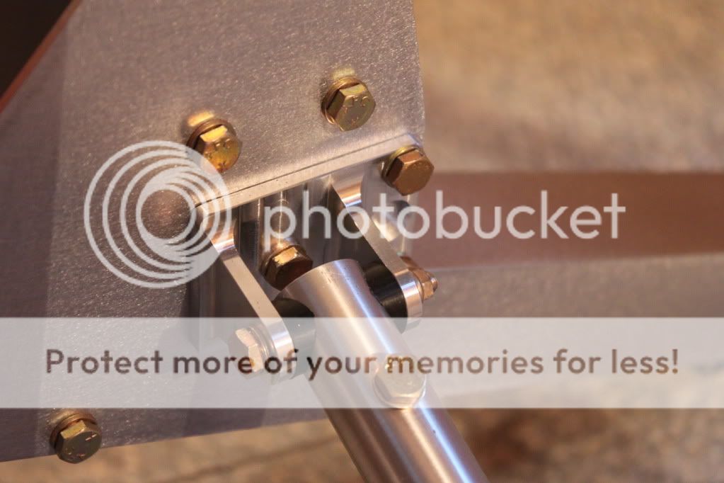
I searched around to find a 2 hole shackle without much luck...And since I would have to match up to the existing holes in the cluster plates, I decided what the heck, and just machined up my own solution.

New Hornet(s) in the works!


I made the ID of the clevis wider, so I could include some nice saddle type Delrin washers to make a nice secure rotating joint for the motion of the landing gear.

I'll try to post one more tidbit yet tonight if I can.
It feels so good to posting updates again!! (And I have A LOT MORE!!)

Take care,
Denis
 
Last edited:
Hey Denis, good to see you posting again!
I've been wondering what you were up to under all that snow. The machine is looking great, you do very nice work!
Are you doing any extra airframe kits? I remember quite a number of folks were interested.
Hang in there and keep pluging away, the snow will soon be gone!:D
 
Next Picture test

Next Picture test

Next change.....

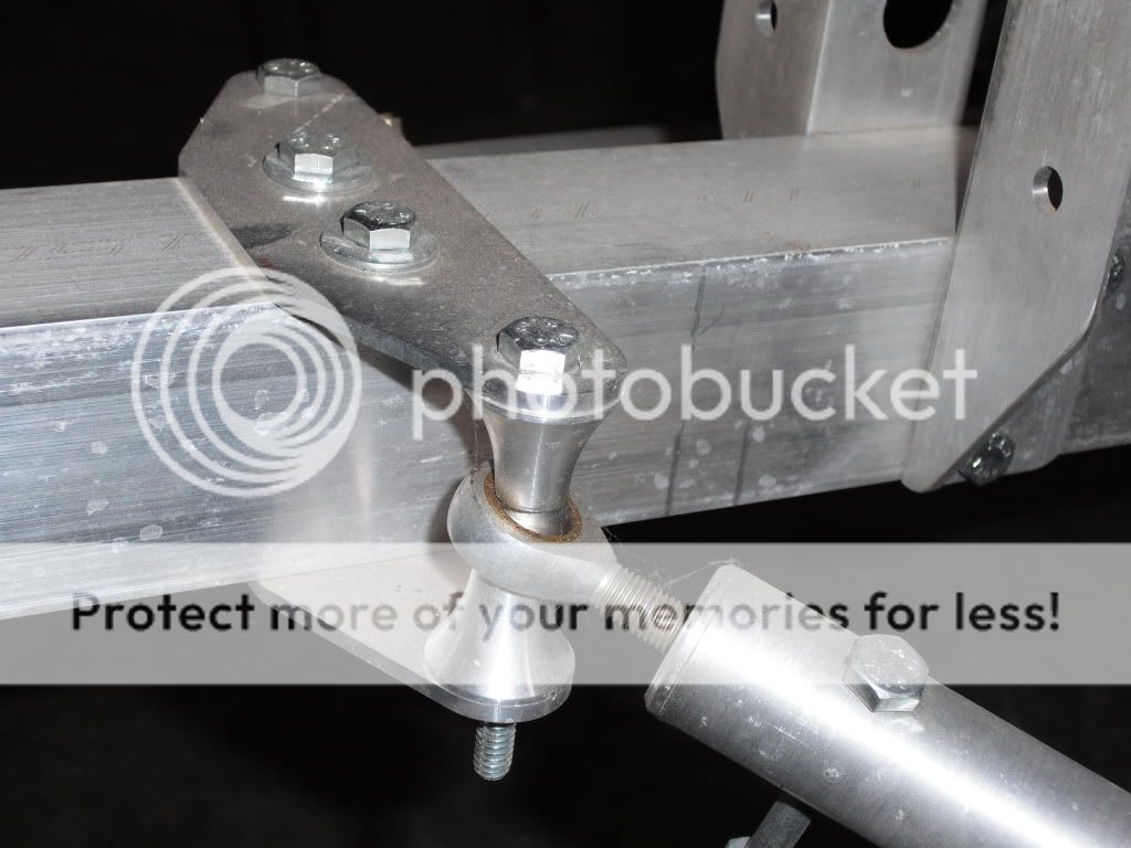
For the drag link mounting, the plans called for such as below...
You can see that even with this temporary 1/4" bolt, (instead of the 5/16" that the rod end needs) which allows the spacers to shift sideways, the rod end bearing is maxed out in rotational travel...Not good...
Yes, I could use a rod end that allows slightly more rotational travel, but it still didn't seem right...


New Hornet(s) in the works!


So, back to the shop....

New Hornet(s) in the works!


New Hornet(s) in the works!


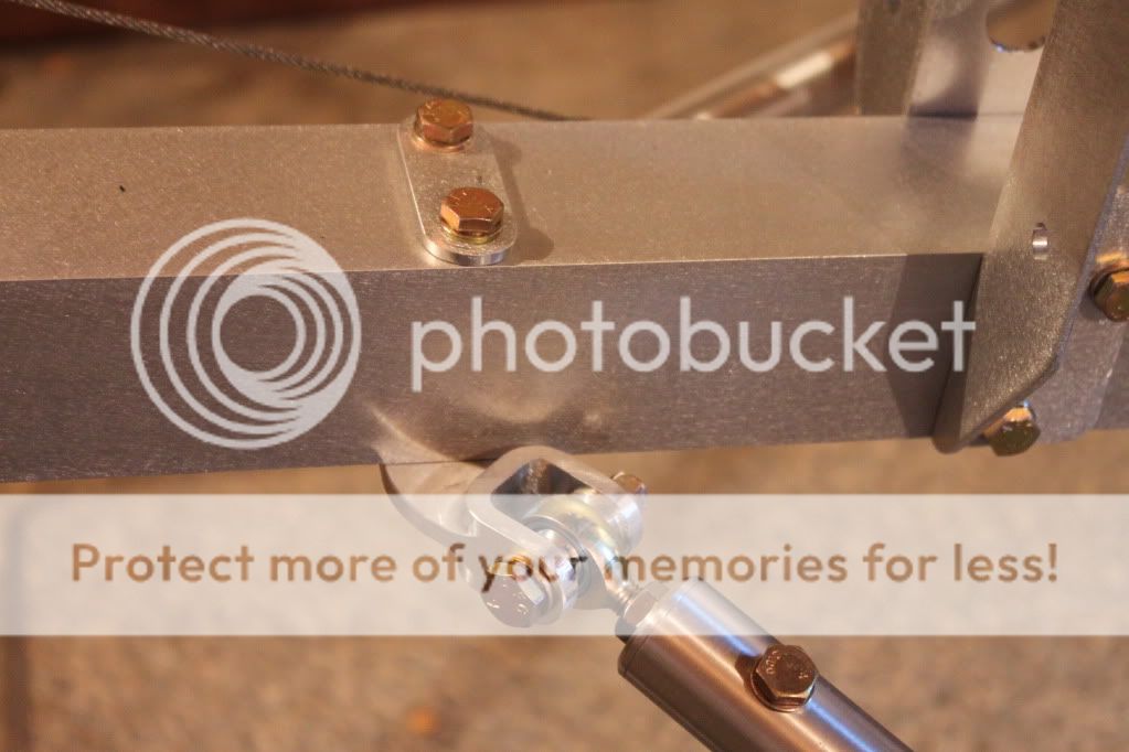
I changed the design to a bracket which would position the clevis portion at the required ~48ish Degree (I'm not at my cad computer now) angle... Now, the rod end only has to swivel around its main axis, and I will never run out of travel!

New Hornet(s) in the works!


I put the little re-enforcement plate on the top just to help take some of the bolt load.

Denis
 
Last edited:
Wow that turned out very nice Denis! Nice solution for the maxed out Heim. This is so much better and the force is directly in the center of the bracket. Nice work and a much better solution than the original! Nice seeing you back and posting :)
 
That is quite an improvement, how long did it take to mill that down? Looks like a must have part now. Very nice work indeed.
Russ
 
Thanks!

Thanks!

Pete,
Thank you!
I don't know why it took me so long...(It really doesn't take that long to type up a quick post)
But it does feel good to be active again on the forum!

No snow here!! This is actually the mildest winter we have had here in many, many years. Just a few random patches of snow on the ground.
A big change from last year. It feels good, but gives the illusion that spring is almost here....Not so...:eek:hwell:

I am still building parts for 3 machines. My own, and 2 more for other Chapter 13 members. I have no plans for providing a kit at this time. (Way too much time involved) Also, liability and my inexperience in the gyro world....
Maybe someday.

Maybe now that I have the machine programs written and ready to run on some of my "tricked-out" parts, I could offer those to anyone interested. But it is still a matter of available time....Just ask Gil how long it took me to get him a few parts he requested!!

Thanks Gabor!
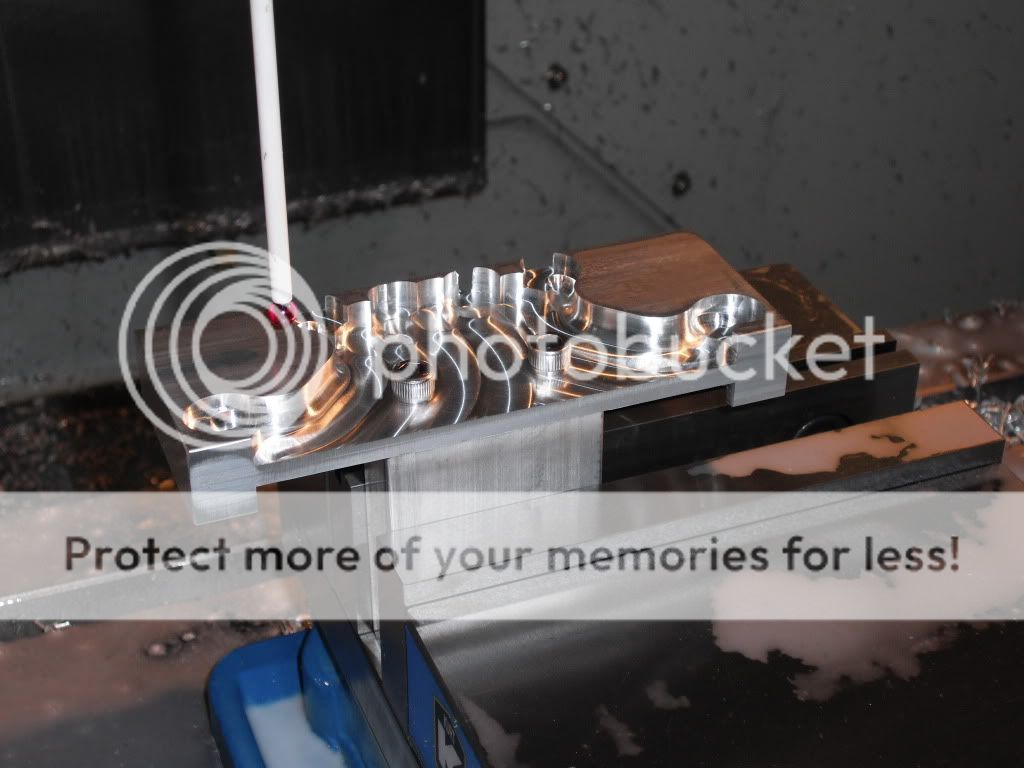
Yes, I feel much better about this design. I tried to think of simpler solution by just offsetting the top an bottom plates, but this would require angled spacers and also some angled wedges under the bolt head and nuts. Then, the hole in the plate would have to be egged-out as well....Not pretty... So my more involved solution seemed to be the simplest that I could come up with.

Russ,
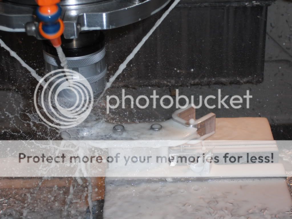
The machine time was not that bad at all....Actual machine run-time was probably only 10 minutes or so.......Its all design, programming and setup time. (Probably 3-4 hours)
You can see in the one picture how I had to mount it on a post to get around it for the final profile.... Much more time involved in the setup than the machining itself.

d
 
Denis had missed seeing you and your build thread on the Hornet's.

Not only has this particular build thread made me feel positively Neanderthal about our own Hornet and its build, but has once again filled me with awe of what some people are capable of doing. There are some truly wonderful artists/craftsmen on this Forum who make magic in their dreams and work in fabricating their machines. Any artistry I may possibly possess is strictly in conducting them around the sky, I struggle with the build.

Your renewed efforts to keep us up with what you are doing with your Hornets (I don't know of any private individual who is doing more than one gyro project simultaneously; two would certainly be laudable but three is really tearing butt!!:yo:) is certainly greatly welcomed by all of us.

Your improvements were needed and certainly look very elegant and efficient solutions to the shortcomings that are in the present design. Yes our machine flies however your tweaks certainly improve the safety aspect and who would not applaud that.

Looking forward to more on your progress on both the machines...and in flying yours once you get to that stage.

Wishing you all the best.
 
robo_nipsy : It has got to be one heck of a machine to do all the work I have seen. Also how long have you been doing this? When you were cutting out the tall tail ribs my machine is much much slower. it would have had a fit if you would have asked it to go that fast... Part looks great!
 
Top