New Hornet(s) in the works!

robo_nipsy

Active Member
Joined
Dec 9, 2008
Messages
323
Location
Mankato, MN
Aircraft
Gyro Technic
Hi all,
It's been a while since I posted....I was lurking a few months back and then had a few posts stating my intentions to start build a Bee... Thanks to all who welcomed me and even shared some cad drawings with me! Much appreciated.
Since that time I have joined the Minnesota Rotorcraft Club - PRA Chapter 17. A great bunch of guys who have been supportive and inspiring!
So anyhow, after more consideration, and direction from others in the club, I have begun the construction of a Hornet instead.
If anyone remembers me from my welcome mat posts, I have a small business that specializes in custom machine automation. I am fortunate enough to have a full shop with CNC equipment, so such a build is very natural for me, but oh so much more fun than the daily machine components!!!
I am actually doing the machining for 2 airframes. One for myself and one for a fellow club member. (Maybe he will start his own build thread here too).
I have been making parts a couple/few hours a night for about a month now, and I think it is coming along nicely.
I first modeled everything up in 3D first... It gives me a better feel for how things fit together, lets dimension the parts the way I like to enter the dimensions for machining and also add my own little custom tweaks...
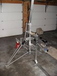
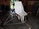
So to get things started, here are a couple pictures of the machine so far...
I will try to keep up with regular posts as the machine comes together!
Thanks
Denis

Pictures:
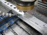
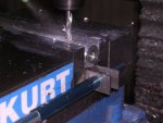
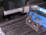
Machining Seat brace......CNC sure makes things a lot easier!!

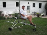
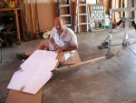
Frame 1.............That is a stack of parts for the other Hornet sitting in the background...and before anyone flames me, yes that is an electrical conduit clamp acting as a shackle for the landing gear! (Just for mock-up only...Promise!!)

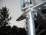
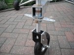
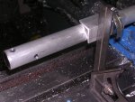
Shock Assy Complete........I replaced the tube and washer components with a machined component much like is used on the bottom of the shock. I used Black Acetal (delrin) for all of the plastic components...A little more expensive, but I think it looks sexier...and more UV resistant too!

More posts to come...
 

Attachments

  • New Hornet(s) in the works!
    Frame 1.jpg
    89.7 KB · Views: 15
  • New Hornet(s) in the works!
    Machining seat brace.jpg
    72.5 KB · Views: 15
  • New Hornet(s) in the works!
    Shock Assy Complete.jpg
    69.3 KB · Views: 14
I love the look of CNC machined parts….it is really looking nice Denis! It is a lot easier to make a series of the larger lightening holes with CNC too…..you lucky duck.
 
I have an old 1975 Craftman 6"x45" lathe and an old Milling machine I just bought. I know what U mean! I love making stuf with my toys. I am going over an KB-2 Benson with a Mac 90 hp on it and I have NO Prop yet. But I am having fun with it by dismanteling it, painting it diffrent colors (to see what it looks like, in matching) and I am almost finish with it. I used my milling machine to build a replacement of the Mag-neto and converting it to Electronic Ing. I Used the lathe for 3 hrs, while building the shaft out of Brass and Nickel. U guys would be impressed. I will send U all pictures later. Have fun, I know I will.
 
Denis delighted to see more Hornets on the way. Was beginning to think that no one finished them by the look of the build logs on the GDT website build log page. Not even sure how many are flying

It was a shame when Dan stopped his as he was really going strong when he had to move. Roy Freeberg made a beautiful job on his but hasn't been too well recently so we haven't seen it flying.

I think it is a great looking gyro and looking forward to seeing yours take shape. I am sure it will do so quite quickly. Also looking forward to seeing all the tweaks you will be coming up with.

Are you going 103? Ours was on the heavy side and realizing that we were not going to make ultralight went ahead and added some bells and a whistle, or two.
 
Very cool, another new build to watch and learn form.

Thanks for sharing...
 
robo_nipsy :
Well you have come a long way in just a few months of building and I have to say it looks good also. Keep the pictures coming so we can see your birds
 
Hi robo-nipsy

This is very encouraging to see all of the building that you are doing, because this brings up a point and a conversation I had about some 40 years ago with a elderly gentleman (about my age now) when I attended a EAA meeting with the intent of maybe joining.

At that time (about 40 years ago) the local chapter of the EAA was looking very good and was not that far away for me to attend if I joined.

As I was visiting with some of the members, I met this gentleman and he told me this chapter wound not be there in 10 years and I asked why not? He said "not enough builders", if you don't have a good number of builders, soon you will not have either a chapter or maybe even an organization. He said you can't hold a chapter together with "buyers and talkers" they just don't have the enthusiasm of a "builder. The chapter had only two builders and this member had been in the chapter about 3 years.

Well, he was right, it didn't last but about 8 more years and it folded as did another chapter and both combined with a third chapter to make one chapter covering a 3 state corner and now that chapter only has a couple of builders and it is on life support trying to survive. I look at our situation every day at PRA and just hope we can get more builders like you. BEST OF LUCK with your building.

Tony
 
Denis, question I meant to ask you in my first post.

Why did you switch from a Bee to the Hornet?
 
Hey everybody,
Thanks all for the input!

Inventer,
Please do post some pictures of you elect ignition project. Sounds cool! And yes, there is nothing that brings such satisfaction as to actually making the parts....I sit at the computer all day designing various components...and although designing virtual models of everything is fun, there is still nothing to compare to the pride and accomplishment of actually getting out in the shop, making some chips fly and producing a physical part!

Resasi,
Yes, the build logs on the hornet site are sparse and infrequent...Seems like a lot of people drop out half way through the build...Too bad.
I don't know if I am going to post a build log on there or just keep it here....We'll see.
I must say that I haven't been following the forum enough lately to know the reasons that some of the builders are being forced to give up their dreams....I know Dan was a very active contributor to the hornet site.

My intention is to try to make 103 for now...It sounds like that is tough to do, but I'll try....If I have to get it numbered, well so be it...And as you said, then I can fit on a lot more "tweaks".

I don't know all the reasons that I dropped the Bee idea and went with the hornet. I liked the simplcity of the Bee. Not to offend anyone here, but there were areas on the Bee that seemed a little "pieced-together" to me....There is nothing wrong with the way the Bee is constructed, but since I am fortunate enough to have access to machine tools which will allow me to produce slightly more involved parts...why not.
I like the drop keel, and the landing gear for sure. I feel Don did an excellent job thinking through the attachment points on the folding mast also.

Clive,
I do all my modeling in Autodesk Inventor 2010. I am able to read most Pro-E, SolidWorks, Unigraphics files plus of course stp, sat, iges, dwg, dxf.....

Speaking of, If anyone has a model of a 503 with a B box that they would mind sharing, It would be much appreciated!

Dog,
Thanks! But actually, I just started cutting the first piece of stock for the keel tube on 7/6/09...So actually I've only been working on it (them) for 4 weeks...
I know I was talking about starting my Bee back around the same time that you started yours, but it took my joining of Chapter 17 and working with those guys to really put a fire under my butt and do something about it!! I'm really hoping I can keep up the pace! I think I will...It's too much fun not to!

Tony,
Thanks for the kind words. Yes, hopefully we can keep the excitement alive. For those of you who don't know, Minnesota Chapter 17 has been re-sanctioned for around 6 months now, It took a lot of hard work by many of the members, and namely our President, Chuck Freese.
We have many builds in process and a lot of excitement behind each one of them!

More progress photos next week!

Thanks
Denis
 
Hey Denis...
Your making me jealous...you'll have that done in no time at all if you keep up the pace Brent and you are going...!
It's looking very nice...but I swear...I'm not gonna race you...(maybe in the air though <smile>).
I'll be stopping by now very soon- so I'll see Ya' then.

------------------
(Back story:
Denis lives a mere 50 miles north of me. He and I are fellow members of the newly revived Chapter-17 in the Minneapolis/St. Paul area.
I purchased all of my Aluminum from him at VERY fair prices and I hope to soon have him construct some of my badly needed machined parts. I whole heartedly recommend his shop services to any of you possibly seeking TOP notch machining services, maybe even to be constructed on his monster Mazak CNC multi axis mill (the thing is HUGE..!).
Send him your CAD files for a quote, maybe he can help Ya' "get 'er done".
No doubt...I'll be sending all my "outsourced" machining services his way.
 
Yes Dan was a great help to us during our build.

Denis I agree, it appeared to me that Don liked the Bee and simply felt that he could perhaps improve upon it. He certainly gives credit to the Bee. Interesting that he seems not to have finished his.

His dropped keel and gear were both items that I liked the look of. We opted to go for the solid mast though in retrospect this may turn out to have been retrograde step. I think the dropped keel may help in extracting more energy from the 503 with the bigger prop.

Look forward to seeing your build progress and good luck with 103. I'm sure with your mechanical knowledge and expertise it will be far more achievable for you than for us.

Glad though that we did opt for certification as we have been able to make some bits stronger and add items we wanted.
 
Update..

Update..

Hi all,
Well the build is coming along....
Brent's machine is further than mine...He has his engine already and maybe even his blades by now!!
I've been working on details when I have the time...
I am going to attach a few picks and some comments for anyone else taking the Hornet path.

Well, It's sitting on it's wheels! Feels good!

A few notes about the front wheel...The plans call out for using a wheel from a Razor scooter. Brent order 2 sets of wheel at once..One set for his, one set for mine. And although ordered at the same time , the rims for the Razor wheel were completely different! On his, the bearings were pressed from the outside in, on mine, the bearing were from the inside out. (You have to separate the wheel halves to get to the bearings)

So, due to the design of my wheel, a spacer was included between the bearings....This spacer was too long from the factory! The two halves would not touch when bolted together because of this. Whoever assembled at the factory tried to however...Stripping out one of the bolts in the process and crushing the bearings. They would not turn at all when we were first looking at it!...The spacer will be modified and new bearings are on the way.
Another thing to watch for is the valve stem. It would be nice if it was shorter. We had to make some additional 1/8" spacer plates to widen the fork out to clear this...(picture) I am also changing the design to use a 10mm stud through this all instead of the 5/16 bolt the plans call for...I will just stack up with the bearings, spacers, forks and all a lot nicer.

I changed the steering yoke to a machined assembly instead of a weldment. I haven't calculated the weight diff yet...Should be close though...I think it looks a lot cleaner! (there will be no welding on this machine)

I started working on some ideas for a different seat design.
I am going to make it out of 18 Ga alum sheet. Should come in just under 5 pounds. I wanted to make a little prototype to fit to my backside before I invest in having the blanks laser cut. (Picture) I still have many mounting holes and gussets to design into it, but I am going to design it to be a direct bolt in replacement for the stock seat... More pictures to follow.

It felt strange sitting on a tape measure to calculate the width of my butt to design a seat around!!!

This is fun!!!

Denis
 

Attachments

  • New Hornet(s) in the works!
    Machined Steering Yoke s.jpg
    42.3 KB · Views: 12
  • New Hornet(s) in the works!
    Seat Mock-up_mounted s.jpg
    52.1 KB · Views: 11
  • New Hornet(s) in the works!
    Front Wheel Assy s.jpg
    77.6 KB · Views: 12
  • New Hornet(s) in the works!
    Rolling Frame s.jpg
    91.7 KB · Views: 13
  • New Hornet(s) in the works!
    Cutting Prototype Seat s.jpg
    72 KB · Views: 12
Dennis, a pleasure to see you forging ahead with your machine so well.

Yes the machined front fork looks much better then the welding.

I am sure that you will have a number of opportunities to tidy things up on the machine.

Having said that I think Don did a good job, I also think however that you are in a position to possibly improve on it, and look forward to seeing these.

Stuart my son had almost no mechanical experience when he started and had never worked with metal before but I think has enjoyed the learning process and I think done a very fine job so far.

We spent all today down at the hanger doing our usual one forward two back, but from starting last year have progressed quite a long way
 
Dennis, I too got the front wheel in like you did and sent it back, I also opted for the 10mm bolt size and even made a notation in my build book for that change and told Don about that as well I do not guess he made the change to the plans. I love the steering arm you made for the front hope you made two of them need one for the tail to but like the looks and simplisity of your inprovement much better.

Dennis, Rassie don't think for one moment I am out of the Hornet build business I will be back with another just as soon as my shope comes down to vergina and I have again a place to build. I just opted for the ability to fly now than having to wait another year to get in the air.

Dennis, please any good changes you have made to the Hornet design I would like to get a copy so on the next build I can do the same. Saves time, effort and money in the long run. I am looking at a CNC from suretite so I will be build in the same mannor for now on just let the machine do it. Looks great and fit perfect every time.

Your two builds are looking great, wounderful jobs you two are doing.

Dan
 
Fabrication pictures

Fabrication pictures

Hi all,
Another installment of my build log....
I forgot I took these pictures which go back a couple of weeks, but I thought I may as well throw them on my hornet build thread. Maybe it will help somebody out.

The axle tube, shock tube, and drag link are all made from 1" x 1/8" wall 6061-T6.
The plans called for the tubes to be drilled..The threaded insert for the rod end bearings is to be machined and cross drilled....and the acetal insert to be cross drilled.... and then the whole works assembled. I did not care for this.

The way I see it, if both pieces (tube and insert) are machined with a slight amount of clearance to allow aligning of the holes for assembly, then when the bolt is tightened, the tubing will clamp down on the insert and essentially be contacting the insert at only 2 points.

Instead, I decided to machine the inserts to the proper diameter to give them a VERY light press fit into the tube. For the acetal (delrin) insert I allowed about .001" press and the aluminum insert was basically right on size...Maybe .0005" over the bore of the tube.
The Delrin presses in very nicely, but make sure for the aluminum insert, you apply a VERY light coat of anti-seeze grease. If you try to press a bare aluminum plug into a bare aluminum hole, you are only going to get it started a little bit before the material starts galling on each other and there it will sit......It will not go in any further and you won't get it back out.....Your only choice then is to scrap the material and start over.:mad:

After I did this, I then did all the cross drilling as an assembly. I feel it is a MUCH more reliable structure this way. (Picture)

I happen to have a collet block with a square body that I used to clamp on the tube for a reference for the 90 degree hole positions. (Picture) After I was done with all the drilling I decided to take a picture of a little alternative 90 degree guide using a piece of angle and a hose clamp (Picture)...I had to laugh when I was installing this because just then I realized that this was a MUCH easier setup to install and maneuver that my fancy collet block....Live and learn.

Speaking of the inserts for the rod end bearings......
I still went with the male rod end bearing in the threaded alum insert, but I decided to use formed threads instead of conventional cut threads.
Attached is a picture showing the difference between a standard spiral point 2 flute cut tap and a form tap of the same pitch (5/16"-24) You will notice there are no flutes on the form tap because it does not produce a chip. (No material is removed)
The thread is formed instead by displacing the material rather than cutting it away. This make for a much stronger thread because the grain of the material remains intact.
However if you use one of these make sure you use the correct size drill bit. Since the tap displaces the material inward, you actually start out with a larger hole that you would with a cut tap.
A standard 5/16"-24 cut tap would use a letter "M" (.295") drill. For a form tap, you would use a letter "I" (.272") drill. This will give you a very strong, approx 65% deep thread.

My strut assemblies turned out to be a nice length. I have good engagement of the rod end bearing (over 2x dia) and there is still 2-3 threads showing beyond the jam nut. Good.


I have not made a firm decision on the mast modifications as of yet (as described on Brent's build thread) but I am leaning on modifying the seat brace attachment points to be of a saddle clamp design rather than the drilled mast ...(I will take experienced advice over my gut feel any day!!!)

Well, I hope Brent and I can keep the pace going...Work is slowly picking up (thankfully) but I will do my best to keep these birds progressing!


Later,
Denis
 

Attachments

  • New Hornet(s) in the works!
    Drilling Drag Links.jpg
    56.2 KB · Views: 5
  • New Hornet(s) in the works!
    Collet Block.jpg
    68.5 KB · Views: 5
  • New Hornet(s) in the works!
    Hose Clamp_Angle.jpg
    72.5 KB · Views: 5
  • New Hornet(s) in the works!
    Cut vs Form Tap s.jpg
    84.5 KB · Views: 4
Denis...
How much more difficult (as a shop task) is it for you to do the "Form Tap" technique rather than the "Cut thread"..?

When I have you do my inserts (the nearly dozen and a half pieces) I'm curious if it would be a HECK of a lot more in costs, or a just bit more, since I'm certain it is a time labor thing.

M-M
 
Mike,
No extra work at all.
The only difference is the tap drill size.
The form tap actually takes less horsepower to feed than a conventional tap believe it or not.
The only other thing to keep in mind is that you should include a slight countersink on the top of the drilled hole if you want the surface of your part to remain nice and flat. Remember, we are displacing material here...It needs to go somewhere.

Denis
 
Top