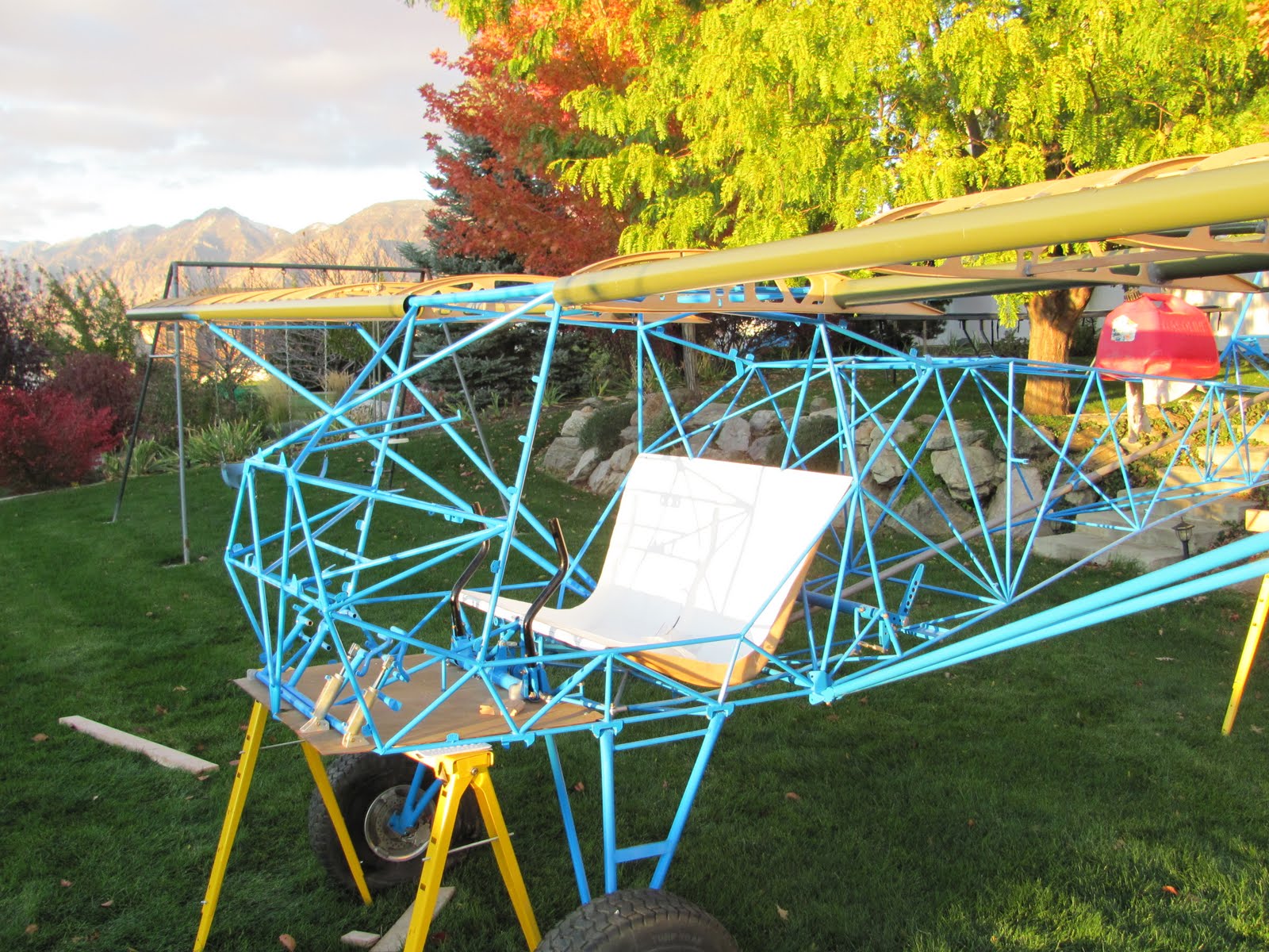
Side-by-Side Little Wing Build

Miranda, can you show me something to look at about your sold design ? Interchangability....wasn't it ?

Good Luck with selling the house ! & your new idea !
 
Hi Rick

I'm certainly not a metallurgist. However, I did research this years ago, the names always seem backwards to me galvanic corrosion I believe is name for the one caused by heat treatment or welding.
IIRC: Intergrunular corrosion occurs with alloyed metals, also known as grain boundary depletions. This occurs when the corrosive alloys are used to create special characteristics in metals what otherwise are noncorrosive like aluminum.

Some of these alloys can be attacked by the elements/corrosion. This makes the metal brittle because it has corroded microscopic veins running through the metal like a spiderweb or gold/quarts veins in rocks.

IA's are grounding the old fleet models when the intergrunular corrosion reaches where the wing spar attaches to the fuselage spar-box.
Only seen planes grounded, so far, that lived on East Cost their entire lives.

I believe this is correct but haven't looked it up in over 10 years at least if not correct one of the pro's will provide the actual answer.:noidea:

Sorry John but you have the definitions reversed.

Doesn't really matter.

All aircraft based near salt air, left or right coast are susceptible to corrosion.

What airframes are usually involved?

Rick
 
Hello All,

My name is Miranda. I just purchased Little Wing plans from Ron Herron, with the express intent of building a Little Wing in the side-by-side configuration. I won't actually begin construction until this summer because I have a couple of other projects I have to finish before then. The delay will give me time to work out the engineering details for side-by-side in the meantime, as well as a couple of other design issues (which affordable engine to use; whether and how to mount stub wings, etc.) that need to be resolved.

I will post ideas I am considering to this thread and, of course, I welcome and look forward to any suggestions, observations, experiences, etc., any of you might want to contribute.

Thanks,

Miranda

Great Idea Miranda.

I have similar thoughts but will start with a different airframe and engine.

Looking forward to your progress.

Rick
 
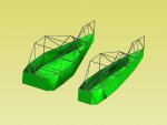
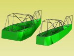
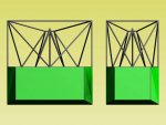
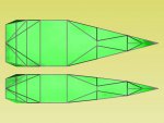
The LW5 at stock 26" and side by side width of proposed 42".

.
 

Attachments

  • Littlewings 4.jpg
    Littlewings 4.jpg
    68.8 KB · Views: 8
  • Littlewings 5.jpg
    Littlewings 5.jpg
    81.3 KB · Views: 8
  • Littlewings 6.jpg
    Littlewings 6.jpg
    78.3 KB · Views: 8
  • Littlewings 7.jpg
    Littlewings 7.jpg
    69.1 KB · Views: 8
John; from the 43.13

6-17. INTERGRANULAR CORROSION.
Inter-granular corrosion is an attack on the grain boundaries of a metal. A highly magnified cross section of any commercial alloy shows the granular structure of the metal. It consists of quantities of individual grains, and
each of these tiny grains has a clearly FIGURE 6-8.

Filiform corrosion. defined boundary which chemically differs from the metal within the grain. The grain boundary and the grain center can react with
each other as anode and cathode when in contact with an electrolyte. (See figure 6-9.)
Rapid selective corrosion of the grain boundaries can occur. High-strength aluminum alloys such as 2014 and 7075 are more susceptible to intergranular corrosion if they have been improperly heat-treated and then exposed to a
corrosive environment.

6-18. EXFOLIATION CORROSION. Exfoliation corrosion is an advanced form of intergranular corrosion and shows itself by lifting up the surface grains of a metal by the force of expanding corrosion products occurring at the grain boundaries just below the surface.

(See figure 6-10.) It is visible evidence of inter-granular corrosion and is most often seen on extruded sections where grain thickness are usually less than in rolled forms.

6-19. GALVANIC CORROSION. Galvanic corrosion occurs when two dissimilar metals make contact in the presence of an electrolyte. (See figure 6-11.) It is usually recognizable by the presence of a build-up of corrosion at the joint between the metals.

There is an AD note on Piper series aircraft where they use a steel attachment strap on the rear aluminum spar. This could be the area that the east coast guys are finding, but if you comply with the AD before the corrosion gets away from you it is not a problem. Unfortunately there are mechanics out there not doing what they billed you for.
 
Thank you Jeff = U-Rock!
I love the people on this site, so helpful!!!
 
Frame off restore huh ? I have a 1982 GMC pickup I am trying to sell for $800. Last guy came to buy it & I couldn't get it started. Kind of ruined the sale !

Been too cold to do anything with right now ![/QUOTE

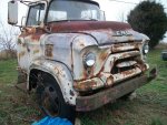
Here is the cab I want to mate to my truck. The 81 Chevy has straight six with the integrated head 250 in it, which I am going to rebuild with a conventional head before installing the cab. Then I'll get it titled at a 1956, hopefully.

I uploaded 3 pics of my donor cab and 1 pic of a cab someone else added to a car hauler - just for reference. Don't know why they attached in different sizes, but you get the idea.

Chris, since you asked, the company I sold my interest in was Just Right Carbines. They have a website at www.justrightcarbines.com. TOS DISCLAIMER: I no longer have any connection to them or any interest in their performance.

It is way too cold here, as well. Schools are closed, and I have a welcome day off.

Stay warm!

Miranda
 

Attachments

  • 1956 GMC COE-LCF Cab 01.JPG
    1956 GMC COE-LCF Cab 01.JPG
    1.4 KB · Views: 0
  • 1956 GMC LCF car hauler.jpg
    1956 GMC LCF car hauler.jpg
    64 KB · Views: 0
  • 1956 GMC COE-LCF Cab 02.JPG
    1956 GMC COE-LCF Cab 02.JPG
    1.2 KB · Views: 0
  • 1956 GMC COE-LCF car hauler 05.jpg
    1956 GMC COE-LCF car hauler 05.jpg
    101.5 KB · Views: 0
Last edited:
Alan, you make it look so easy. What CAD-type program did you use, and how user-friendly is is?

I use TurboCad Pro Platinum version 17 that a friend gifted me with, sometimes these can be purchased on Ebay for less than $250. As with any 3D cad software there is a learning curve but I find it very user-friendly and the Pro Platinum version has many tools that make it's use easier compared to the lower end versions, like the Deluxe I was using.

Being able to "build" the machine in a virtual world is a huge benefit to the design process.

.
 
If your considering using wings to off-load an autorotating rotor you should have a look at this report.

"The influence of wing setting on the wing load and rotor speed of a PCA-2 autogiro as determined in flight"

http://ntrs.nasa.gov/archive/nasa/casi.ntrs.nasa.gov/19930091596_1993091596.pdf

.

VERY interesting. I printed the report out and have been going over it. It pretty well confirms what I suspected would be the case, but it is still very comforting to have the objective data rather than just my own unsophisticated hunch to fall back on.

I ran some numbers calculating lift from both the USA35B and Clark YM-15 airfoils at various airspeeds because I was (and still am) wary of developing so much lift as to excessively unload the rotor system. As an old Huey driver I am still aware of the need to maintain at least a minimum amount of load on the rotor - and it is probably even more important in a gyro since airflow is the only thing driving the rotor RPM.

This brings up a question I have been meaning to ask here. When I flew Hueys and we practiced autorotations regularly, we really had to be careful when doing an auto with a 180-degree turn. For some reason that maneuver tended to build rotor RPM very quickly, and we had to pay close attention to prevent overspeeding the rotor by pulling a little collective pitch as needed to load the rotor during the turn.

I still remember one of my first autos with turn in the UH-1. It was during my Contact phase in flight school, where we transitioned to the UH-1 after our primary training in the TH-55. We entered the auto and were halfway through the turn and before I realized I was in an extreme nose-down attitude and the rotor RPM were way too high. My instructor, a guy named Captain Riddle, took the controls, leveled the aircraft, and pulled in so much collective that I remember feeling the excess G's and looking up through the greenhouse to see if the rotor system was going to remain with us. It did, of course, and we landed safely. He set the aircraft down, lit a cigarette, and took a long deep drag. Finally, he looked at me and said, "I have never, ever, been so nose low in my life." The we went back and tried it again.

My question is whether the tendency to gain rotor RPM in an auto with turn is limited to helicopters in general, certain types of helicopters only, or to all rotary wing aircraft, helos and gyros alike. Any thoughts?

Miranda
 
My question is whether the tendency to gain rotor RPM in an auto with turn is limited to helicopters in general, certain types of helicopters only, or to all rotary wing aircraft, helos and gyros alike. Any thoughts?

Miranda

Hi Miranda,

I just stumbled on this conversation and have been reading through. I think your gyro project sounds very cool. Like others, I'm looking forward to reading about your building adventures when you get started.

I'd like to take at stab at answering your question. I'm no expert on rotor dynamics but I like to think I've got a handle on some of it at least and this is what came to mind in reference to your question. If I'm too off base with this, I'm sure someone will correct me.

Anyway, when you enter a turn in any aircraft, you'll inevitably load the aircraft over the 1 G state that it was in in level flight. On a rotorcraft, that increase in G loading will result in an increase in the coning angle of the rotor system (everything else being equal) and the coriolis effect will take hold and the rotor will naturally speed up. Helicopter pilots can counter this by simply raising the collective a bit. Gyro pilots, at least by my admittedly limited experience, just have to live with it. In the very few hours I have in gyros, it was kind of fun watching the rotor rpm change as the aircraft was maneuvered around but it never seemed to get out of hand. I would think this would be a common effect on any rotorcraft.

FWIW! :)

Best of luck with your project and Fly Safe,
Steve R.
 
Last edited:
I think a Kitfox frame may get you close to your starting point.

17355d1336248295-truss-geometric-efficiency-fuselage.jpg

Dave+Neely+Kitfox+and+Ogden+Temple+004.jpg
 
Last edited:
Wagtail of South Africa is building a Side by Side tractor called the Kriek. For their prototype I believe they used a "Bushbaby" airframe. The Bushbaby appears to be a local made kitplane that is very similar to the Kitfox. Using a Kitfox frame might be a major time saver.
 
Hi Miranda,

if you are interested in the PCA-2 autogyro and winged gyros in general you might want to have a look at our "Technical Papers, Books and Publications" section #84:
http://www.rotaryforum.com/forum/showthread.php?t=32424
http://www.rotaryforum.com/forum/showthread.php?t=32485
http://www.rotaryforum.com/forum/showthread.php?t=32486

I have added one more report which seems to be no longer available from the naca reports server.
http://www.rotaryforum.com/forum/showthread.php?p=560716#post560716

There is one very interesting article available through the Emerald report service (for just a couple bucks more..., see below ;-)

Last but not least there are the incredible works by Franklin D. Harris:
http://www.rotaryforum.com/forum/showthread.php?t=32431
http://www.rotaryforum.com/forum/showthread.php?t=32435

I have also developed a program which calculates trim states for rotary wing aircraft, including winged autogyros. Below you will find attached the standard input file to my program. If you fill in the numbers for your project I would run a number of flight cases for you and would also provide results for flights that have been recorded for the PCA-2. That way we could verify the results obtained through my program as well as, hopefully, get some design data for your project.


Good luck with your project!


PS: just for fun, a few pics here: http://www.rotaryforum.com/forum/showthread.php?t=39535
 

Attachments

  • Fixed_Wing_Gyroplane_Article1938_PCA-2.png
    Fixed_Wing_Gyroplane_Article1938_PCA-2.png
    18.2 KB · Views: 2
  • PCA2.txt
    9.3 KB · Views: 1
Last edited:
My question is whether the tendency to gain rotor RPM in an auto with turn is limited to helicopters in general, certain types of helicopters only, or to all rotary wing aircraft, helos and gyros alike. Any thoughts?
My idea regarding this question is related to another thread where we have discussed the fact that any aircraft loses height in a turn if no power is added, so for an aircraft in pure autorotation the only way to add power is to start and dive. The dive angle depends on the aircraft, current CoG position and loading.
 
Adding Energy

Adding Energy

... in pure (UNPOWERED) autorotation the only way to add power is to start and dive...

A dive does the exact opposite. It unnecessarily consumes altitude and converts that potential energy to increased downward vertical velocity. Because a dive makes the incoming air more from the front, this tilts the total force vector aft of the axis of rotation and SLOWS the Rotor RPM.

RAISING THE NOSE on the other hand slows the descent and converts the saved potential energy to increased rotor RPM because inflow is coming into the rotor from a direction less frontal and more underneath.

This tilts the total force vector more forward of the axis of rotation and acts like a "cranking-rope" on a lawn mower, to increase the rotor RPM.

Amount of coning of the rotor stays practically constant over the green Rotor RPM range. Coriolis doesn't vary much so RPM change due to Coriolis Force is negligible.
 
Some observations and an opinion.

Some observations and an opinion.

VERY interesting.

This brings up a question I have been meaning to ask here. When I flew Hueys and we practiced autorotations regularly, we really had to be careful when doing an auto with a 180-degree turn. For some reason that maneuver tended to build rotor RPM very quickly, and we had to pay close attention to prevent overspeeding the rotor by pulling a little collective pitch as needed to load the rotor during the turn.

I still remember one of my first autos with turn in the UH-1. It was during my Contact phase in flight school, where we transitioned to the UH-1 after our primary training in the TH-55. We entered the auto and were halfway through the turn and before I realized I was in an extreme nose-down attitude and the rotor RPM were way too high. My instructor, a guy named Captain Riddle, took the controls, leveled the aircraft, and pulled in so much collective that I remember feeling the excess G's and looking up through the greenhouse to see if the rotor system was going to remain with us. It did, of course, and we landed safely. He set the aircraft down, lit a cigarette, and took a long deep drag. Finally, he looked at me and said, "I have never, ever, been so nose low in my life." The we went back and tried it again.

My question is whether the tendency to gain rotor RPM in an auto with turn is limited to helicopters in general, certain types of helicopters only, or to all rotary wing aircraft, helos and gyros alike. Any thoughts?

Miranda

I will try to address your question with my observations Miranda.

In every gyroplane I have flown the rotor rpm increases in a turn.

I feel it is because the rotor is more heavily loaded and it responds to that load with increased rotor RPM.

It is my observation that all the gyroplanes I have flown have a much wider rotor rpm range that is acceptable compared to the helicopters I have flown.

In the two place tandem gyroplane I fly I have seen a low of 275 rotor rpm and a high of 450 rotor rpm. I consider this a normal rotor rpm range and confine my maneuvering to this rpm range.

I fly a 1,400 pound gyroplane that used to have 135 horsepower Lycoming o-290 and I found the climb performance wanting in rough air. We installed a used $6,000 160 horsepower Lycoming IO-320 and she went from climbing out at 300 feet per minute to 700 feet per minute at a gross weight of 1,400 pounds. In my opinion you will be much happier with power north of 100 horse power even with your stub wings.

Good luck with you project, Vance
 
...In every gyroplane I have flown the rotor rpm increases in a turn.

I feel it is because the rotor is more heavily loaded and it responds to that load with increased rotor RPM...

In the hundreds of turning autos I did to the ground during my Army training, and in the dozens of turning autos I did in my civilian training to a 3 foot hovering power recovery...

...The ONLY reason that was ever discussed for having to add pitch to avoid the rotor overspeeding, was the change in the angle that the resultant relative wind enters the rotor system. A slight amount of aft cyclic to cause the turn causes a slight change in the entry angle of the relative wind...which adds a tremendous amount of rotational force to the blades.

Now I do admit that the most recently FAA Published Advisory Circular says the reason for RPM increase is the increased load on the rotor.
 
Top