Weber 750 & Megasquirt ECU

Maybe this is the wrong forum, but has anyone come up with a good informed estimate as to total engine weight?
Like Tony I do remember a rough weight = not all components needed were included IIRC it was around 100+ lbs and about 21"x21".

But would need to look it up again as I did not commit it memory as it was not all components. I'm waiting for Tony or others to finished and weight one if possible.
 
HI Jeff

Is that "unconverted weight" without the gearbox and adapter and mounts ?? What's the all up weight on a 582.

Tony
 
Hi Tony

It weighs 60.3 lbs or 27.4 kg wo/ exhaust, carb, fuel pump, radiator!
Here are all of the specks.

WEIGHT: Engine: wo/ exhaust, carb, fuel pump, radiator .lbs.......( 27.4 kg.)
2 Carburetors with flanges...........4.0 lbs.......( 1.8 kg.)
Exhaust system............................11.2 lbs.......( 5.1 kg.)
OPTIONAL EQUIPMENT: 2 air filters..............................................0.6 lbs.......( 0.3 kg.)
Double air filter.......................1.1 lbs........( 0.5 kg.)
Intake Silencer with filter...........2.4 lbs........( 1.1 kg.)
Integrated Radiator System
(#881-432) ...............................4.6 lbs........( 2.1 kg.)
Electric start kit, PTO side .......7.5 lbs........( 3.4 kg.)
Electric Start kit, MAG side .........9.9 lbs.........( 4.5 kg.)
Reduction box "B" (dry).....................17.6 lbs........(8.0 kg.)
Rotax 582 Specifications DESCRIPTION: Two cycle, two cylinder, rotary valve engine, oil-in-fuel lubrication or oil pump, liquid cooled, with integrated water pump
BORE: 76.0 mm (2.99 in.)
STROKE: 64.0 mm (2.52 in.)
DISPLACEMENT: 580.7 cc (35.44 cu. in.)
COMPRESSION: Theoretical: 11.5 - effective 5.75
POWER OUTPUT: 48 kw (64.4 HP SAE) at 6500 1/min
TORQUE: 75 nm (55.3 ft. lbs.) at 6,000 1/min.
MAX RPM: 6800 1/min.
DIRECTION OF ROTATION Counter- clockwise, viewed towards PTO
(Clockwise with Reduction installed)
CYLINDER: 2 light alloy cylinder with cast iron sleeves
PISTON: aluminum cast piston with 2 piston rings
PISTON/CYLINDER CLEARANCE: 0.06 mm (.0024")
CHT: Cylinder Head Temperatures
(Optional Values) Normal: 110 C - 130 C or 230 F - 270 F
Maximum: 150 C or 300 F
Max. Difference: 10 C or 45 F
EGT: Exhaust Gas Temperatures Normal: 500 C - 620 C or 930 F - 1150 F
Maximum: 650 C or 1200 F
Max. Difference: 25 C or 45 F
Crankcase Temp. Max.: 80 C or 175 F
Cooling Liquid Temp Max.: 80 C or 175 F
IGNITION SYSTEM: Breakerless Ducati Capacitor Discharge Dual Ignition with magneto generator
GENERATOR OUTPUT: 170 Watts AC at 6000 RPM and 13.5 RMS
IGNITION TIMING: 1.96 mm or .077" (18 BTDC)
SPARK PLUG: 1.96 mm or .077" (18 BTDC)
ELECTRODE GAP: 0.5 mm (.02")
ROTARY VALVE TIMING: Opens: 130 BTDC Closes: 50 ATDC
CARBURETOR: 2 x Bing 54 36 mm Slide Valve
FUEL PUMP: Pneumatic fuel pump
FUEL: Regular or Premium Gasoline, octane number not below RON 90 (unleaded)
ENGINE LUBRICATION: Oil-in- fuel with Super two-cycle oil ASTM/CEC standard, mixing ratio
REDUCTION GEAR LUBRICATION: Gear oil API-GL5 or GL6, SAE 140 EP or 85W - 140 EP
PROPELLER SHAFT DIRECTION: Clockwise, viewed towards prop flange
STARTER: Rewind Starter Standard
STANDARD VERSION INCLUDES: Engine with carburetors w/ clamps, fuel pump, exhaust system
 
That is the weight with basic engine and ECU, wiring sensors etc. It does not include the gearbox or adapter.
 

Attachments

  • Weber - 009.jpg
    Weber - 009.jpg
    10.4 KB · Views: 0
  • Weber - 024.jpg
    Weber - 024.jpg
    11.6 KB · Views: 0
Low side #'s
(64HP - 110HP) = 46HP increase with a weight increase of (118 lbs. - 60 lbs.) = 58 lbs.

That is impressive isn't it when compared to the overall aircraft weight?

High side #'s
(64HP - 140HP) = 76HP increase with a weight increase of (118 lbs. - 60 lbs.) = 58 lbs.

This is VERY impressive although would this higher setting reduce TBO?

Then consider the price about $5K+ for a four stroke 100HP Webber compared to a Rotax 100HP 912 @124lbs $15.5K or even the 914 @141lbs $28K.
 
Last edited:
phase two of fuse block wiring

phase two of fuse block wiring

Well this is where it gets difficult to explain even with pictures, but I will do my best, (there is a reason for all this detail, will explain later).

In the first picture are the different terminals that are involved with the wiring of the fuse block, the first is the ganged group of 5 terminals, part # 12160661, the next is the terminal that is used for the relay contacts, part # 1205870, and the third terminal is the one that is used for the relay coil connections, part #12065894 .

The ganged terminals are used for the fuses that are "buss" fed and the single terminals for the same fuses are cut from a gang set. The fuse block is set up to that the buss feed comes to the fuse first and then to the relay and then to the load (thru the relay closed contacts). There are 6 fuses (2 are spares) and 4 relays giving one fuse for each relay. Three fuses are "gang" fed by "primary buss" (master switch for battery) and one fuse is fed by "secondary buss" (ignition switch). Three relays are "gang" fed by the "primary buss" but activated by "logic ground" from the ECU. The 4th relay is fed by the ignition switch and has a "fixed chassis ground" so it operates when the ingnition switch is turned on. The other 3 relays close when the ECU says everything is "go" and sends "primary buss 12 volts" to the associated load ( injector, ignition coil, ). The associated load (injector, ignition coil )then is operated by "logic ground" from the ECU, the fuel pump relay is operated by ECU logic ground ---BUT THE FUEL PUMP IT SELF HAS A CHASSIS GROUND !!! This allows the ECU to shut off the 12 volt to the fuel pump if the ECU fails.

The last 3 pictures are an attempt to show some of how the wiring is done. Note, there are 3 wires entering the fuse block, a 12 guage primary buss, a 16 guage secondary buss and a 16 guage black chassis ground. The little 12 guage jumper at end of the block is tying the two gang terminals together (I cut off a couple of unused insulation grips just to clean things up. There are 3 terminals on each gang with single terminals interspaced giving a fuse set up for each gang terminal. Everywhere you see a 12 guage "jumper" , it is going from a fuse to one contact on a relay (the other contact goes to the load). You will notice a "looped" jumper of 16 guage that comes from one of the gang strips, it feeds 12 volt buss to 3 relays. You will also note a single 16 jumper that feeds a single relay with a chassis ground, this is the ECU relay. The 16 guage "secondary buss)feeds the relay coil. Oh yes a after thought, the terminals all come from Performance Connection Systems.

I will comment on the relays in the next post.

Tony
 

Attachments

  • Building the fuse block and power center 027.jpg
    Building the fuse block and power center 027.jpg
    54.6 KB · Views: 0
  • Building the fuse block and power center 028.jpg
    Building the fuse block and power center 028.jpg
    58.1 KB · Views: 0
  • Building the fuse block and power center 029.jpg
    Building the fuse block and power center 029.jpg
    49.4 KB · Views: 0
  • Building the fuse block and power center 030.jpg
    Building the fuse block and power center 030.jpg
    60.4 KB · Views: 0
  • Building the fuse block and power center 031.jpg
    Building the fuse block and power center 031.jpg
    66 KB · Views: 0
Last edited:
no engine yet.
the hydrospace is a flat crank turbo.
I would think you can use the ecu that comes with the water engine it is made to run more like a airplane than a snow machine.

You sure about that?
The snow machine ecu is ready for both big temperature and altitude changes
Good for up to 12000 feet altitude!
Not many hills or temp changes on a lake!
Snow machines get lots of WOT with high resistance as well!
Also get a lighter exhaust instead of the wet exhaust and make 155 Hp
Besides a snow machine can top a sharp hill and fly a good 50 feet!:plane:
Just had to put that in there!:lol:
 
relay information

relay information

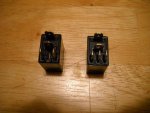
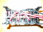
the relays that came with the original Polaris fuse block are single pole normal open. The brand is "SONG CHUAN" I recommend you stay with this brand because it is a SEALED RELAY, other brands just have snap on covers and are not moisture proof. NOW--------I can not find the original relay part # 871-1a-S-R1. The 1a designated single pole normal open, however Mouser has this relay in designation 871-1c-S-R1,----the 1c designated single pole double throw. You will note in the picture of the relays, one relay has 3 of the smaller blades and the other has only 2, the one with the 3 blades is the single pole double throw, it has a rating of 30 amp /20 amp (30 amp on the closed contact and 20 on the open contact side. ALL OF THE RECEPTICALS FOR THESE RELAYS HAVE THE THIRD POSITION AVAILABLE , just don't put a terminal in it..... These relays are less than $2.50 each and can be obtained from www.mouser.com part # 871-1c-S-R1

The 3rd and final stage of the wiring will be mating the fuse block to the harness and this will really get "messy" but will try to post something usable with pictures.

I have gone to all of this detail to try and show just how much work is involved in making the harness. The basic Microsquirt with harness is now about $ 390 , a hell of a buy, add another $100 or $150 for all the parts and connectors and fuse block and it is still a good buy but if you want a clean neat set up you will have to do quite a bit of work to make the harness!!!!!!

I point out all of the above because there is no doubt in my mind that someone is going to produce the motor mount, the gearbox adapters, and dampers. Neil at Autoflight already produces the adapter and flywheel and damper for the one piece crank style engine. Hopefully in a few weeks I will have the adapter and flywheel for the flat face crank style engine along with the MaZAK computer program for the adapter. I don't expect Neil to produce a casting for the flat face crank until a market justifies it, so until then it will have to be machined from billet.

when all of this is available you will be able to have a Weber mounted on you bird in about 2 days or less, -----but until someone produces the harness-------you can add at least 2 weeks and a lot of work before it is ready to run.

With Randy out at www.weberpower.com offering new engines (both the normal aspirated reversed head Redline model and the HSR turbo at around $5000 it is clear this is really getting SERIOUS .

Tony
 
Last edited:
I know that in real life conversions from rotax 582 to jabiru 2200 engines, the weight is equal, the jabiru is 120 lbs or so. Just trying to work out the weight for use in my fixed wing, The 912 rotax can be used but it takes some lead or stretching the airframe. delete if unapropriate
 
Canadain rhino I see all the guys using the snow engine are not using the stock ecu and wires. I think it has to many other things we dont need going on . I agree with you it will run fine and adjust for alt. I'm not looking to flight about it just saying form what I see. But the water ecu is doing what the snow will do without all the other things we dont need.

I don't have an engine to play with yet to test what I think so we may never know. Im looking for a good 912, 914 replacement and this weber engine looks like it is up to the task. If I am is stll to be seen. I'm glad your posting what you know about the engine from riding one and letting us know if any troubles pop up.
 
I would like to use a rotax cbox on one, they are all over the place so getting one and parts for it will not be hard or take along time to get.
 
C-Box is the way I will be going. One more project to finish after todays test flight of a M35 Blonanza.
 
Hi Eric

I'm interested in seeing the Weber used in any application that will be benifical to experimental aviation. Although I am a "tractor gyro" type, at the moment my personal "push" is to see the first Weber in a Genisis as soon as possible.

Once I get my adapter housing back from the machine shop I will be looking for someone that will consider not only machining the housings, but weld up the motor mounts and exhaust system and provide a supply source for anyone interested. Anyone prepared to do this will be considered to get the MAZAK program that I will have for the housing and the info on the flywheel. I think all of this needs to be done by one source, the wiring harness is another story.

Tony
 
Last edited:
I think Mark"s adapter housing is for the Rotax "C" box, it is quite similar to mine for the Autoflight box.

Tony
 
Canadain rhino I see all the guys using the snow engine are not using the stock ecu and wires. I think it has to many other things we dont need going on . I agree with you it will run fine and adjust for alt. I'm not looking to flight about it just saying form what I see. But the water ecu is doing what the snow will do without all the other things we dont need.

I don't have an engine to play with yet to test what I think so we may never know. Im looking for a good 912, 914 replacement and this weber engine looks like it is up to the task. If I am is stll to be seen. I'm glad your posting what you know about the engine from riding one and letting us know if any troubles pop up.

I dont understand which sensor you dont need?
Sounds like your ecu would make my sled run terrible.
the weber is in a class of its own beating 1000 cc 2 strokes all the time
Nice engine and no noise and go like a bat out of xxxx
If this dosent work out for you are you going to blame the weber or this other added ecu?
See my point?
I have a lot of miles on these machines and know what they like and dont like
Polaris didnt put anything on for sensors that wasnt needed in my opinion!
 
I want to try the ecu that comes with the weber hydrospace engine so not adding one. It was made for this engine. You know the engine always get the blame for anything bad that happens.
 
If Two Stroke International still made the gearbox they used. It would be good for the flat faced PTO engines. I used one on the aircooled BMW bike engine. anyone have one?
 
What I like about Neil's universal gearbox is that it couples to the flywheel without any spline mechanisim so there is no place for any type of wear. This is accomplished with the three radial bolts in the damper. A little more difficult to assemble but worth it to me. Of coure if you are using a centrifugal clutch it's a no-brianer.

Tony
 
Last edited:
NOTICE-NOTICE-NOTICE

A very very deceptive wiring situation exsist with the Weber MPE-750 if you are using the Microsquirt or Megasquirt EFI systems. It is not difficult to deal with, it just can catch you off guard very, very, easy and give you a real headache trying to find out what is wrong.

The Weber uses 2 timing inputs to the ECU, one is the crankshaft timing sensor and the other is the cam shaft sensor.

The the Microsquirt ECU gives 2 options for the crankshaft sensor ---- one is a hall effect sensor the other is a VR sensor, ---- the Weber will use the VR sensor. The crankshaft VR sensor on the Weber has a long pigtail lead coming out of the sensor and has a connector already on it and the pigtail is molded into the sensor. Examination of the schematic shows there are 3 terminals in this connector, 2 wires and a shield ground covering the wires. This is because the output from this sensor is AC and produces RFI that can interfere with other sensor inputs, so it is shielded. The shield in the pigtail is not connected to ground at the sensor, it is floating (fortunately) and was to get its ground from the connecting wiring. NOW--- here comes the sneaky part, the wire coming from the Microsquirt VR circut is a "mini" coax, it has ===ONE ===wire in the center and then the shield. If you connect the shield from the Microsquirt to the shield terminal on the pigtail you will have an "open circut" , a no-go situation or a incomplete input to the Microsquirt VR circut. NOTE THIS POINT--- Microsquirt is very emphatic about the fact that it uses TWO DIFFERENT ground system, one is chassis ground and the other is a SPECIAL SENSOR GROUND and the two should NEVER be tied together !!!!!!!! What you must do is use the 2 wires in the pigtail, connecting the white wire to the center conductor terminal of the "mini" coax and the black wire to the "shield" terminal. Now----- this leaves the "pigtail" portion of the crankshaft sensor with a "floating ground" or same as no shielding. You can use two options, 1. connect a 16 or 18 guage wire with a "eye" terminal to the third (shield ) terminal with enough length to reach a convienent grouning point on the engine block. or 2. you can go a more difficult way that may give better shielding and that is to install a braid shield over the "mini" coax, grounding it a a convienent location and let the braid shield and the shield on the pigtail connect at the mating connectors.

BTW-BTW----- the only place I have been able to find the correct mating connector for the sensor pigtail is through Mercedez Benze ( I have the part number but can't find it right now)

Tony
 
Top