RRPM - Searching for some explanations

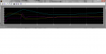
Nicolas, I entered 340 rpm for 7.3 mx 0.216 m 2450N, 25 m / s
It gives me A.o.A (disk) = 9.7 °, a1 = 2.14 °, B1 = 1.16°, rotors pitch = 3.2 °, retreating blade is stalled until .45 R

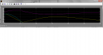
Now, when I give the disk 25 °, the lift of 17.5 m / s and 265 rpm is 2130 N, a1 = 2.6 °, b1 = 1.25 °, retreating blade is stalled until .7 R.
Accelerating torque: 260 Nm
 
Last edited:
and what is the flapping angle at 265 rpm?
 
The results presented below show the transient response of a gyro to a control input. The stick is pulled back and returned to normal position after 5 seconds. The figures probably only give a correct trend since these are the first runs of my dynamic gyro model but it is quite interesting to note that it takes about 15 seconds for the inflow to return to the value it started out from. From these results I would deduce that it might be difficult to get a good static approximation to the problem.

The figures show (left to right)
- longitudinal swash plate angle B1
- rotor Z force
- inflow
- rotor speed (rad/sec)
 

Attachments

  • stckMvmtChart.png
    stckMvmtChart.png
    11.5 KB · Views: 0
  • fMRChart.png
    fMRChart.png
    11.2 KB · Views: 0
  • lamiChart.png
    lamiChart.png
    9.6 KB · Views: 0
  • rrpmChart.png
    rrpmChart.png
    10.2 KB · Views: 0
Last edited:
Nicolas, The longitudinal flapping is a1 = 2,6°, flapping on the side is b1 = 1,25°

Now, R.p.m minimum for lift 1800 N (2450 N with propeller help) : 218 r.p.m with A.o.A = 35°, forward speed= 18,5 m/s. So, the retreating blade is totaly stalled between azimut 30° and 150°, r.p.m acceleration is 0 and flapping angle is 4,5°. This is what gives my spreadsheet.

Juergen, Do you assume that during this 30 seconds, the structure does not pitching? How is this possible?
 
Last edited:
Since this is a full 3D dynamic model all attitude changes about the three spacial axes are included.
Here are the angular rates (left) and Euler angles (right). Pitch changes are in magenta.
 

Attachments

  • elrDot.png
    elrDot.png
    13.3 KB · Views: 0
  • elrAnglChart.png
    elrAnglChart.png
    11.5 KB · Views: 0
I understand, Juergen. So, your initial condition is:
-Longitudinal swash plate angle : - .11 rd (-6.3° )
-Force Z : 4310 N
-Inflow : 5,55 x 10⁻³ (0,81 m/s ?)
-R.p.m : 33,5 rd/s (320 t/mn)
Well. It is probably a rotor of 8.8 x 0.216 m with a pitch of 4° flying at 35 m/s (68 kts)
Now you put back further -.205 rd (-11,7°) during 5 seconds.
I obtains immediately 5200 N (1,2 g), then increasing since r.p.m increases. While you obtains only 4420 N (1,025 g) decreasing. With inflow from 5.5 exp-3 to 8 exp-3, rrpm should increase, right?
This is not surprising?

Jean Claude
 
Last edited:
I obtain ....... While you obtain....... This is not surprising?
I don't think it is surprising that we get different results. If you increase the rotor disk angle of attack the rotor H force increases and slows down the gyro, in this case from 26.5 m/s to about 23.2 m/s. Since you do not seem to perform a time integration I take it that you assume the flight speed to be constant which in turn means you increase the power output of your engine and thus impart a constant air speed to the rotor, thus accelerating it. As I said: this is a fully coupled 3D analysis.
 
Since you do not seem to perform a time integration I take it that you assume the flight speed to be constant
Yes Juergen. But increasing inflow, integrated in the first five seconds, would it not increase continuously rrpm? Instead rpm increases and then decreases during these 5 seconds. That's what I do not understand.
 
Last edited:
Rotor speed and inflow change in tight unison
Juergen, the inertia of a rotor of 80 lbs requires more than 5 seconds to reach the value corresponding to inflow. How can it take inflow in tight unison ?
 
Change in rotor speed is not constant but changes with the moment applied. Following your suggestion I have checked the inertia of the blade and the torque coefficient in my program, both are correct. Until further evidence I will therefore assume that the aerodynamic moment is simply large enough to bring about the rapid change in rotor speed we see in the model. One might want to keep in mind that this change happens at nominal rotor speed where large aerodynamic forces are acting. The time constant for flapping (which is also a rotation of the blade) is 0.07 sec at the extrem. (Padfield page 35)
 
Last edited:
Juergen, I have not read Padfield, Prouty, Gussow because too for Google translator. Just my thoughts: If the time constant rotation was the same as the time constant flapping, then pushing forward the stick to 0 g, the rotor should stop in 0,07 second. Of course wrong. My spreadsheet shows to me (a posteriori) a time constant rotation of 10 seconds, and 0.11 s in flapping.
 
Last edited:
JC, how are calculating the induced flow in your spredsheet?
 
Raghu, Is a major challenge for me to calculate the velocity induced.
With small angles of rotor A.o.a, I calculate with the formula:
Induced speed = forward speed x CL disk / (Pi. 1,27). (1,27 is aspect ratio to disk)
Then empirical corrections for to give results closer to reality with an axial flow.
Also correction of flux distribution for zero speed induced a leading edge of the disk, and double to the rear edge.
 
Last edited:
There's nothing wrong with developing a new method of inflow calculation. If you want to check your results against the formula that has been used by all others over the last seventy or so years you can use formula 14 of the report below. Use formula 12 to calculate cT. If you plug in your values you should get the same figure on the left and right of the equal sign.
http://arxiv.org/ftp/arxiv/papers/0804/0804.3895.pdf

Happy simming!

Juergen

Jurgen, JC's formulation is just as old, well known, and valid. If you assume mu to be much greater than lambda, equation 14 reduces to the formulation given by jc. The trouble with equation 14 is that it is circular and as such can only be solved iteratively. If you assume a reasonable forward velocity (anything over twice the induced velocity in hover; over 30 mph in a typical gyro) both formulations give you virtually identical answer.


Anyway, the reason for my original question is both formulations do not take into account dynamic non uniform variations of the induced flow which are Important in the kind of transient maneuvers you are talking about here. In other words you are not going to get the answer you are looking for with such a simple model of the induced flow.
 
you are not going to get the answer you are looking for with such a simple model of the induced flow.
That is why one of my next steps would be to introduce the Pitt/Peters/He inflow model in my dynamic simulation. Do you have experience with it?

The trouble with equation 14 is that it is circular and as such can only be solved iteratively
I just thougth that if you already have a solution it would be a quick sanitiy check to plug in the values into the formula and see how close the left and right hand side of the equation are
 
Last edited:
Top