Power Push Over (PPO)

May I meddle with Greg's last paragraph?

The thrust to overcome the airframe's drag during a power-off glide is provided by the rotor. In such a glide, the rotor disk's leading edge is lower than its trailing edge. A vector component of the total rotor thrust is horizontal, pulling the gyro forward against airframe drag -- just like a helicopter. Bensen makes this point nicely in his gyroglider manual, including a side view of a gliding gyro clearly showing the forward tilt of the rotor relative to the horizon.

In a steady glide, the rotor's (tipped-forward) thrustline will be positioned relative to the aircraft's CG so as to create a net zero pitching moment on the frame. This may dictate that the rotor thrustline is ahead of, or behind, the CG, depending on the location of the airframe's center of drag relative to the CG. A low airframe center of drag will require rotor thrustline ahead of CG and vice versa.

Since the rotor must fly at the angle of attack it needs to hold the gyro up (no more and no less), the location of the CG relative to the rotor thrustline is accomplished by the flight stance of the airframe. For example, if the rotor thrustline needs to be ahead of the CG, then the CG will swing back relative to the rotor until this is so. The situation is a mirror image of the HTL/LTL balancing act.

The location of the prop's center relative to the CG will make a small difference in the aircraft's stance in a glide, even if the prop is idling or stopped. An idling prop becomes a drag brake at higher airspeeds. The location of the center of the prop thus will affect the location of the airframe's overall center of drag. The prop disk is just one of the draggy items on the frame. This is another reason why large displacements of the prop centerline away from the CG -- whether HTL or LTL -- are not a good idea: any moment about the CG created by the prop actually reverses direction when the power is chopped at higher airspeeds.

Everything cancels out once a steady state glide is reached, but the transition can be hairy and (I think) even dangerous in a poor enough design.
 
Vance, one more thing - how close to the edge?

Vance, one more thing - how close to the edge?

-----I have not been able to find an airspeed that I am uncomfortable with. One of the things I wonder about is how close to the edge I am.

Close to the edge?

I feel the best determination of where the "edge" of the safe operating envelope - power/airspeed combo - is whether your gyro still feels comfortable in moderate turbulence with a "fixed stick". This would be where the gyro is inherently stabilizing the gyro itself – without need for pilot intervention or skill. If the gyro no longer provides comfortable flight in (its worst case) “fixed stick” mode, the pilot must be the stabilizer and make it feel comfortable. Often the subjective judgment of a pilot that “it feels good” is simply due to the skills the pilot has developed to “stabilize” the unstable gyro yourself. If increasing airspeed fixed stick starts getting uncomfortable, and you feel you must take control again, IMO, that is a good indication that your gyro is losing its inherent DYNAMIC stability. The normal slow rate phugoid oscillations are not being damped back to nothing - but instead keep growing where they become uncomfortable. IMO, that is an indication that the AOA (and G-Load) STATIC restoring pitch moment is getting weak. (When there is no STATIC AOA restoring moment, the gyro will no longer oscillate in disturbances - it may actual diverge (buntover?) in response to a disturbance - no longer a Static restoring moment that would prevent the buntover.

To test this, first devise a way to "fix the stick" safely. We have been recommending a small link chain anchored to a very solid point forward of the stick - the instrument panel? Wrap the chain a turn or two around the cyclic grip and squeeze it to hold it under your hand. In flight, with the stick held back and the chain tight, the length of this chain should set the test airspeed - more forward stick faster airspeed. Practice releasing this chain to regain control of the stick - should be quick. This arrangement allows roll inputs to keep the gyro level, while restricting the stick from normal pilot pitch inputs.

Then start at moderate power and MPRS (Minimum Power Required Speed) S&L flight with the chain held tight on the grip under your hand. Moderate afternoon turbulence will excite some phugoid (normal and slow) oscillations. The gyro should, and probably will at MPRS, feel very comfortable - inherently damping the oscillations. Repeat this with the stick "fixed" in this position at both full power (climb) and idle power (gliding descent). At MPRS, any gyro with a HS ought to feel comfortable.

Then, repeat the above at about 5 mph increasing airspeeds. If a gyro is going to become unstable, DYNAMIC stability become neutral or negative, and the STATIC restoring moment approaching zero, it is going to do it at higher airspeeds. Depending on effective LTL or HTL, this might occur at lower power or higher power.

When you find an airspeed/power combination where it feels uncomfortable in turbulence - "fixed stick" - that indicates the gyro is approaching the condition where, beyond that airspeed point, may lose its Static AOA (and G-Load) stability completely. Pushed much beyond this airspeed point at that power level, it may become more susceptible to either buntover or PIO - with the right (wrong) disturbance and/or pilot input. That speed point, where it becomes "uncomfortable” with a "fixed stick", should be your Vne for that power setting.

If/when you find that uncomfortable point, you can release the chain and stabilize the gyro yourself. This should not be difficult for you to do, but realize, pushing to higher airspeeds than this - YOU are the stabilizer, not the aircraft. If you venture beyond this Vne, you are relying on your skills and proficiency, your senses and reactions to keep you safe. You may never find an uncomfortable airspeed/power combo - that would be best. If you do find this point, make that your Vne, and respect it. If you don't, and especially in rougher winds or perhaps a sudden power change, you might not have the skills and reactions to stop something bad before it happens.

If you want to widen your speed/power envelope, the easiest thing might be to move the HS further aft. A longer moment arm for the HS aft of the CG increases the DYNAMIC damping by the square of that moment arm – move it further aft by 10%, and DYNAMIC damping is improved by 20%, while STATIC restoring moment is improved by 10%.

- Greg
 
May I meddle with Greg's last paragraph?

Doug, some great fine points - and I don't think I have any issues with your descriptions. There are often various and valuable ways to present these things. And, you always have a great (and shorter) way of explaining such things. Even if you disagree or correct me, I really appreciate the thoughtful critique or restatement. I hope you will always let all of us know where you might have a differing opinion.

One feedback I could use: Do you agree with me or with Chuck that the airspeed will adjust to a new trimmed (fixed stick) airspeed upon power change - or will it simply be a transient disturbance that will eventually settle back to the original power airspeed? I'm thinking about working through all the static forces and moments equations to see how the static steady state pitch and airspeed settle out (return to balance) with different power (prop thrust) levels. I did this a long time ago for a series of “envelope” articles I wrote, but I want to do it again from scratch, seeing if I can take Chuck's rotor effects into account. That will take some quality time I will try to find. But, I'm always looking for brain exercise to help ward off Alzheimer's anyway!!!!!

- Greg


- Greg
 
Greg, my experience with Dominators is that, when you add power, they slow down unless you add -- and hold continually -- forward pressure to the stick. This is not a stick-locked test, though. What's probably going on in this case is that the nose swings up, stretching the trim spring (by pulling on its lower end) and adding aft trim force to the control system. If you lock the stick, though, the trim spring (and the rest of the gimbal head) become inoperative and no longer matter.

I don't know how completely rotor blowback fixes the rotor's airspeed, stick locked, regardless of power setting. I would think that might depend on the particular flight characteristics of your given rotor (even without any added weirdness from pitching-moment-induced twisting) -- but there may be a hard-and-fast rule about the blowback effect. I'll take a peek at Gessow and Myers if I get a chance.
 
Chuck and Doug. I am sure you know all that, but I feel we need to get back to the basics. Aeronautical engineering convention describes lift (L) as a vector perpendicular to the flight path - not a vector opposing weight (W). Draw a schematic showing the lift perpendicular to the flight path in descent, and the RTV will be a vector tilted back ~10° from the lift vector, same as in level flight. The RTV may very well be pointing forward relative to the horizon, but it will always be tilted back relative the flight path.

Now draw a weight (W) vector coming off of the CG and break the weight vector into 2 vectors - Wsin(gamma) and Wcos(gamma). Gamma is the angle of descent. Wcos(gamma), is perpendicular to the flight path and is opposed and equal to the lift vector. Wsin(gamma), is the vector opposing airframe drag AND rotor drag (both drag vectors are parallel to the flight path, of course). Yes, the rotor is not pulling the gyro forward, it is still opposing the flight path by ~10°. What is pulling the gyro forward (relative to the air flow) is the partial gravity vector Wsin(gamma).

If D1 is airframe drag and D2 is rotor drag, Wsin(gamma) = D1+D2

In a descent with power, T+Wsin(gamma) = D1+D2, where T is prop thrust.

I hope this brings some clarity to this discussion.

One more thing - even during power-off descent the CG is not necessarily aligned with the RTV. Only if there are NO pitching moments about the CG will the CG be aligned with the RTV. Off-center drag, sloping windshields, HS, all can and do create their own pitching moments. I am not so sure these are negligible as compared with a mild prop thrustline offset. Lacking any other evidence, the SH windshield might be a significant pitching factor, being countered only by a huge stab immersed in prop wash. The unbalanced rotor is probably not helping matters, but the fact that during S/L flight the gyro is stable tells me the rotor is not the whole story. It is a combination of things.

Udi
 
Last edited:
Oh what the heck. I don't have time to make computer drawings but I am attaching a hand schematic showing the above on paper. Please forgive the messy scribbles.
 

Attachments

  • Trim Spring SL vs Descent.pdf
    42.4 KB · Views: 0
Thanks you guys!!!
 
I understand, Udi, that the engine in a power off glide is the potential energy of height being consumed. But the force of our sled running downhill comes from the reaction of the runners against the snow. A rotor running in air isn’t all that different. A paraglider (is that the right name for a flying parachute?) would look about the same.

My sketch did show the rotor tilted ~10º aft of the flightpath and drag as parallel to the flight path.

I chose to use horizontal and vertical as reference axes rather than axes parallel and perpendicular to the flight path, thinking it might be simpler that way.

This still doesn’t address the issue of why an otherwise stable gyro speeds up with power reduction and slows with a power increase.

Velocity stability is the derivative of pitching moment with respect to flight path speed and is entirely the result of rotor “blowback.” As airspeed increases, the rotor tilts rearward, creating a nose up moment about the CG and the opposite when slowed. FW aircraft, naturally don’t possess velocity stability and speed stability comes entirely from angle of attack stability.

If a gyro otherwise possesses angle of attack stability, velocity stability provided by the rotor can be excessive and cause over compensation; ie., slow down with a power increase and speed up with a power decrease.

What can be done about excess speed stability without compromising angle of attack stability? McDonnell Aircraft attacked the problem of excess velocity stability on their XV-1 convertiplane by the use of a pitch/cone coupled rotor based on patents of Friedrich von Doblhoff, the Austrian pioneer of tip jet propulsion. An increase of disc angle of attack and resultant coning angle increase was coupled to blade incidence in a manner that reduced incidence. Pitch/cone coupling is not to be confused with pitch/flap coupling.

There’s quite a bit about the XV-1 on the internet; Here’s an article in Wikipedia.

http://en.wikipedia.org/wiki/McDonnell_XV-1
 
Hey ya'll, this is some great stuff!

Udi, good to have you back. Terrific explanation in post # 132.

As Chuck so kindly stated above, back in the day when I was trying to learn something about this stuff, I filled up a composition book with notes trying to understand and explain the interaction between trim spring progression rate, offset and air speed stability. Now you come along and explain with crystal clarity in a just few lines what I filled half a note book with.:sad:

Then down in post #145 &146 you show me how to express all that mess in precise mathmatical terms! Folks, it don't get much better than this!:peace:

Greg G. brings up a very important point concerning some "other variables".
At one point I had fine tuned my machine to a state of perfect "harmony". (to me) This thing was sheer delight to fly. I was so pleased, I worked out some charts, formulas, ratios ect., to chisel it all in stone. Then a friend brought over some rotor blades of another brand to try. Just about everything I thought I knew ... flew right out the window! But I finally worked it out and learned some more. BTW; if you make provisions on your torque bar to adjust the distance between the pitch pivot and upper spring attachment, you can fine tune the spring progression rate. (Udi's "spring constant (K)" ;) )
Some seemingly insignificant airframe mods can screw up the whole equation. It seems that anything that changes the airframe MOI or affects the rate of attitude change will put you back to re-tuning. As Greg said, it can get very complicated!:yo:
 
Vance, I'll try to keep this brief - huh!

Someone please tell me this is valuable to them - I need to know my time is helping someone, otherwise, I need to be doing other things too!

Thank you Greg.

I always learn something from you, even when I don’t agree with your point of view.

I appreciate it very much when you take the time to answer my simplistic questions.

I covet your ability to sound knowledgeable.

I value your glossary of terms.

I am not alone in my appreciation of the time you take to share your opinion.

Thank you, Vance
 
Thanks, Pete! I appreciate the complement - you are my hero :first:

Chuck - of course one may analyze the problem with a different set of axes, I didn't intend to suggest otherwise. The way I described the vectors makes it easy (for me) to visualize and calculate RTV and it's components - lift and drag - at any angle and with/without power. You mentioned at some point that when airframe drag equals the weight of the gyro the angle of descent would be 45°. This sketch shows that the sum of airframe AND rotor drag must equal the weight of the gyro for gamma to be 45°.

But the whole purpose of this exercise for me was to show the relationship between the angle gamma and trim spring tension -trim spring tension being an indication of rotor AOA vs. the airframe. Rotor AOA vs. the airframe is THE primary airspeed control in a gyro.

This still doesn’t address the issue of why an otherwise stable gyro speeds up with power reduction and slows with a power increase.
ok. This is going to be long and tedious, so proceed at your own risk.

Lets assume a very LTL (VLTL) gyro flying S/L trimmed at 65 MPH. I am exaggerating a problem in order to make a point. The pilot is gradually reducing power to idle. What happens? Lets assume centerline drag and no other aerodynamic pitching moments. Before the power is reduced, the RTV is passing way behind the CG in order to balance the VLTL nose-up pitching moment right? There is no other way for this gyro to be balanced. RTV passing behind the CG really means the stick is more forward than where it would be had it been a CLT gyro. Being at trim airspeed means the trim spring tension is such that it is balancing the RTV, with the given gimbal offset geometry. But also remember that this trim spring tension is constant at this specific angle between the rotor head and the airframe. If you locked the stick at this angle, the gyro would continue to tread along at the same airspeed even without the spring.

The power has been removed. The balance of moments has been disturbed and the gyro is pitching nose down because the RTV is still behind the CG. If the stick were locked, i.e. if you have fixed the rotor head to the airframe, how would the RTV become aligned with the CG to stop the nose down pitching? Would the gyro do a forward flip? What is the mechanism that achieves this? The only mechanism, with a locked stick, is that, as the gyro is pitching nose down, it accelerates, which causes the rotor to blow back, the RTV to move fwd, until it has (hopefully) moved forward far enough to become aligned with the CG. BUT - this will happen at a higher airspeed than 65 because at 65, the RTV was a few inches behind the CG!

That's explains it with a locked stick. Now, what happens with a free stick?

When the stick is free the rotor head changes it's angle vs. the airframe as a function of the rotor thrust. Whenever the RTV is reduced, the rotor head pitches nose-up and slackens the spring until a new equilibrium is achieved between RTV and spring tension. During descent, part of the weight of the gyro is supported by airframe drag, which reduces the rotor load a little. As I showed above, this might translate to actual rotor head movement, depending on the spring constant. A stiff spring would enable very little rotor head movement in response to the reduced loading and the gyro would behave very much as if the stick were fixed. i.e. the gyro would have to accelerate fast enough to induce sufficient rotor blow back to move the RTV fwd until it aligns with the CG. A soft spring would cause the rotor head to pitch back and help to bring the RTV forward - back in line with the CG - at a lower airspeed than if the stick were fixed.

I wanted to talk about a full-power climb, but this post is becoming way too long and I know people don't have patience for long posts so I will stop right here for now. Have I answered the question?

Udi
 
Greg, in response to your question, yes we are learning and the continued responses by Chuck, Doug and Udi are putting it all in perspective. Now to be honest, do I get it, all I can say as I'm trying my best to understand and learn and hopefully it will start to sink in. I do thank each of you for continuing to provide this in-depth education and thought provoking insight.
Russ
 
Udi, no one is arguing the effects of gross propeller thrust line offsets on pitch behavior vs. power change.

But the issue is how can LTL of 2” cause airspeed runaway, assuming both assertions are true?

We need to hear from Carl Schneider whose new gyro is exactly CLT.

How about it Carl; with stick locked, does your airspeed remain constant with a power chop?

One of my uncompleted projects from at least 10 years ago was to explore the effects of variations of CG vs. propeller thrust line. To that end, I obtained a pair of 20 lb. lead ingots with the intent of strapping them to the suspension struts at various heights. But the best laid plans…….. gang aft agley.
 
But the issue is how can LTL of 2” cause airspeed runaway, assuming both assertions are true?
Well, part of the answer to this question might be to ask what is the actual blow-back angle of a given rotor as a function of airspeed. I may be wasting my time on that but I have spent a couple of hours now, trying to calculate the BB angle as a function of airspeed. Not easy to do without some serious elemental analysis. The results I got don't make much sense - I get a BB angle of 0.85° at 65 mph and 1.25° at 100 mph. This seems to low, but I have no real data to compare my results to. Do you have any suggestions?

Udi
 
Udi, to perform a meaningful analysis, you’d get into some nice partial differential equations and spend the rest of your life counting squares if a paper solution was attempted.

The stall of the retreating blade spreads outward as a function of Reynolds number as well as angle of attack and has considerable hysteresis between stalling and unstalling.

My spread sheet shows flapping angle to be 2.06º at 65 mph and 3.91º at 100 mph with 30 ft. rotor, 9” chord and 1200 lb. AUW but don’t take that to the bank. That also assumes an airfoil with a zero pitching moment coefficient. Neither does it does it account for blade stall, a major factor in the higher speed ranges. Or for yaw angle of relative airflow.

Surely NASA and some universities have rotor programs that run on their super computers that provide meaningful answers.

For us tinkers, about the only useful results might be obtained by measuring trim force and relating that back to thrust line/pitch bolt offset.
 
So much home work to do . . .it makes me sick of my stomach.
Not easy to translate all that.
Thank you guys!
Heron
 
Let's work with your numbers, Chuck. Assume 2.06º at 65 mph and 3.91º at 100 mph. If the guys that tested the SH in a dive have started the test at 65 mph and "chickened out" at 85 mph, it would be reasonable to expect the blow back angle to have changed from 2° to 3° over this speed range. If you assume a gyro weight of 1100 lbs, prop thrust of 350 lbs at 65 mph, and a prop thrust line offset of 2", the RTV would have to swing fwd about 0.7° in order to compensate for the loss of nose up moment.

Lets add to the mix some nose-down pitching moment from the sloping windshield. The windshield is located about 2.5 ft ahead of the CG. In order for the windshield to swing the airframe back 0.3°, it would have to produce 11 lbs of nose-down force. Is it reasonable to assume that the windshield is producing at least 11 lbs of down force? If the answer to that is yes, than this is your answer.

Windshield pitching moments should be countered by the stab. But the stab may be partially blocked by the cabin. This may explain why adding "some" power gets the SH out of the dive - in addition to adding pure nose-up pitching moment, it powers the stab, which negated the windshield moment.

I don't think there is much more than that going on.

Udi
 
Last edited:
I hate to disappoint you and Al, Udi, but those simple expressions simply don’t work for flapping angle as a result of retreating blade stall.

At a peripheral tip speed to forward speed ratio of ~0.35, some 70% of the retreating blade will be stalled and the stick will be on or near the forward stop. It will simply refuse to go any faster because flapping angle vs. forward speed becomes nearly a vertical line. The flapping angle increases exponentially with forward speed.

I can’t post pictures right now (recovering from a computer crash; did something dumb) but you may recall the NACA material I’ve posted previously that shows the measured stall region of the retreating blade of a Kellett KD-1 Autogiro vs. airspeed.

I’ve also had hands on experience with retreating blade stall before I had much understanding of what was happening. Way back in the beginning (for me), I adjusted the pitch of my Bensen type blades up to the stops, don’t remember the angle but they were still startable.

My gyro became the most peculiar flying contraption imaginable. It wouldn’t go faster than 20 mph with the stick jammed right up against the forward stop; it simply screwed itself up and down with power change. Some of my fellow flyers did the same with their Rotordyne blades with similar results. I would be surprised if Pete Johnson hasn’t done the same. Perhaps people aren’t as inquisitive now as they were 30 some years ago.

What was happening was that the flapping angle was on the vertical portion of its curve and acted like the friction governor of a wind up phonograph. Flat bottomed blades having lots of camber will autorotate at amazingly high pitch angles.

That’s the reason I say a gyro can’t have runaway airspeed so long as the rotor blade profile in one with zero pitching moment coefficient.
 
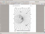
Udi, attached is the plot of retreating blade stall as measured by the NACA. They mounted a motion picture camera on the rotor head and using the sun as an azimuth marker, plotted stall by observing silk streamers attached to the rotor blade.

What do you think the cyclic flapping angle might be with 70% of the retreating blade stalled?
 

Attachments

  • Blade stall.JPG
    Blade stall.JPG
    61.1 KB · Views: 0
Last edited:
Top