Alan Cheatham - Keep in mind that a spring or damper will only reduce spike loads and not static loads.
Although the material properties of a weld are far from those of the base material
welds stand up quite well to static loads. German design codes allow a plastic
deformation of 1% for a weld, which is five times the technical yield point (0.2%).
That's why, in all the years I worked as an FEM analyst in the railroad industry,
I have never seen a vehicle fail in a static load case. There may have been a little
warping in parts of the vehicle but the welds did not crack.
Repeated load cycles are another story. Especially with fillet welds you need a very
low number of cycles with a high stress level ( greater than let's say one half to
three quarters the yield strength) for a crack to develope. I therefore assume that
the crack in the predator is not from a static load and in my opinion it would be
worth while to bring down the peak load.
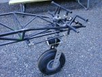
I have carried out a little sensitivity analysis for the structure, i.e I do not want to
find out the actual stresses in the part (you'd need much more data for that) but
to compare stresses for different load cases and design variants. In the attached
pictures the y-direction of the coordinate system is along the strut the z-direction
runs along the center line of the aircraft and the x-direction points sideways. For
each load case I applied a force of 1000 N in one of thedirections.
Results are:
A lateral load (x direction) causes negligible stresses in the T joint.
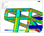
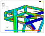
For the y direction this load gives a stress of about 12N/mm² in the T joint between
gear strut and upper cross beam. (picture 'BTR_Fy1k_dlt1.png'). A force of 1000N in
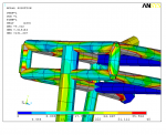
z-direction causes a stress of 40 N/mm², i.e. stresses are almost four times higher
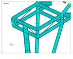
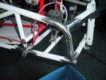
for a z load than for a y load. The reason can be seen in picture 'BTR_Fz1k_defoScl1NN'
where the deformation of the structure is scaled to one hundred times the real value.
The picture shows that the two cross tubes are beeing bent and that the four longitu-
dinal tubes sag.
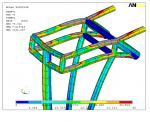
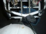
When the structure is braced like in picture 'BTR_Fz1k_ovw3.png' the stress in the
upper T joint is reduced to about 30 N/mm².
I would sum up results like this:
- the design has quite some potential for improvement.
- bracing helps a bit but does not solve the basic problem
- forces in y and z direction must both be considered in the design of the joint.
Cheers,
Juergen
.