Jean Claude
Junior Member
- Joined
- Jan 2, 2009
- Messages
- 2,599
- Location
- Centre FRANCE
- Aircraft
- I piloted gliders C800, Bijave, C 310, airplanes Piper J3 , PA 28, Jodel D117, DR 220, Cessna 150, C
- Total Flight Time
- About 500 h (FW + ultra light)
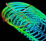
1. Please note the downwash (DW) is only a transient feature. If you look at the lower right side of the picture you will see that the streamlines are almost exactly the same as the lower left side. Hence Lift has been produced but the effect is short lived and so the streamlines have returned to normal. This suggests that the picture in Post #3 is not entirely accurate.
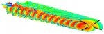
The photos you show are for a section between two partitions. Ttherefore, they are representative of an infini aspect ratio, for which the DW is nul. This is not the case of a disk, for which aspect ratio is 1.27, So, DW is extended numerous diameter in rear as in my picture.