Trim spring tension

C. Beaty

Gold Supporter
Joined
Apr 16, 2004
Messages
10,101
Location
Florida
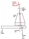
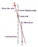
The required trim spring tension of a Bensen type rotorhead is primarily a function of cyclic flapping angle (rotor “blowback” angle). It has little to do with rotor lift/drag ratio.

As airspeed increases, the cyclic flapping angle normally increases, moving the rotor thrust vector nearer to the pitch pivot and reducing the amount of necessary trim spring tension.

Cambered rotorblades with insufficient trailing edge reflex suppress cyclic flapping and require more trim spring tension. The advancing blade, having greater airspeed than the retreating blade, twists nose down more than the retreating blade, reducing angle of attack and the amount of flapping required for lift equalization. Acts like a built in swashplate.

Rotorblades with a nose up pitching characteristic behave in the opposite manner. Bensen wood blades had excess reflex and the advancing blade twisted more nose up than the retreating blade, increasing cyclic flapping angle and moving the rotor thrust vector nearer to the pitch pivot. They would typically give a neutral stick without a trim spring at 50 mph.

Rotorblades are long and skinny and can’t be made so stiff that twist is not a factor if there is a residual pitching moment.
 

Attachments

  • offset.JPG
    offset.JPG
    18.2 KB · Views: 97
Chuck Beaty and Pete Johnson and a few other very smart people figured out the workings of the Bensen gimbal head long, long before patent drawings of Cierva's offset gimbal invention were available on the 'Net. Kudos to them. In at least one old article, Igor Bensen claimed to have thought of the offset gimbal setup himself.

The gimbal head puts the phenomenon of "rotor blowback" to work to give the rotor an airspeed stability that it otherwise would only have at zero MPH airspeed. By using some extra offset and a trim spring, the exact airspeed that the rotor will always seek can be adjusted by changing the spring tension.

But, wait, there's more: The offset gimbal also provides the tilting-spindle rotor with angle-of-attack (or G-load) stability that it entirely lacks otherwise. A random increase in rotor thrust caused, say, by an updraft, results in an increase in the upward pull exerted by the rotor spindle on the torque bar/tube. Just before the increase, this thrust and the spring tension balanced each other. With the increase, the thrust pulls UP harder than the spring pulls DOWN. The torque bar tips forward enough the increase the spring tension and restore the balance of forces.

Here's where it gets interesting: This "re-balancing" mechanism works only if the pilot allows it to. The pilot's grip must be light enough to allow the stick (connected rigidly to the torque bar) to move forward on its own. Hence the notion of "floating the stick" by using a very light grip: this technique frees the gimbal head to do its holy work.

Yet more: The spring tension in flight is obviously critical to the workings of the gimbal head. The torque bar changes spring tension by pulling or relaxing its pull on the upper end of the spring. That leaves the LOWER end of the spring to think about. It's normally clamped or clipped to the airframe. If the aiframe pitches in a certain direction, that movement, too, will change the spring's tension. In particular, if the frame pitches strongly nose-up in an updraft, the frame will pull on the lower end of the spring and INCREASE the spring's tension. This, in turn, will pull DOWN on the torque bar and can overwhelm the designed tendency of the bar to tip forward when rotor thrust increases.

IOW, a sufficiently unstable airframe can sabotage the beneficial effects of the offset gimbal head design. The gimbal head works best with a pitch-neutral or pitch-stable airframe.
 
Chuck

Thanks so much for volunteering this information. I understand completely about this phenomenon now for the first time, as you explained it so clearly and succinctly.

Hats off.
 
So glad I check the forum today for PM's.

Great thread my friends. Thank you for teaching me so much. You and Doug ROCK!!!
 
Thank you, Chuck, for this very enlightening explanation! Yours and Doug's arguments seem to be well founded. To me it seems that every contemporary autogyro has an offset gimbal head, but the one thing I find puzzling is that the influence of an offset gimbal head on stability does not show up in the equations. The Glasgow report states:
All light gyroplanes fly with what are basically slight variations in the design of the
Bensen rotor head. A feature of the design is that the teeter mechanism is not
mounted directly above the rotor hub pivot point, but is displaced aft by a few
centimetres. This endows the aircraft with a degree of stick-free stability when
disturbed by, say, atmospheric changes. All the analysis conducted here assumes
stick-fixed, and it is the case that stick-free the aircraft is more stable. Trim
differences (Figure 7.31) are limited to pitch attitude and rotor tilt, while Section T
compliance (Figure 7.32) and time responses (Figure 7.33) both confirm that this
parameter has a negligible impact on the dynamic stability and response of the
aircraft.
If that is true the effect would seem to be one that is rather felt by the pilot than a real augmentation of flight stability.

Looking forward to the comments from the forum.


PS: in an old "flight" article I recently read that Ken Wallis held a patent for an offset gimbal gyro rotor head. It would be interesting to know exactly who contributed what to today's designs.
 
Last edited:
Juergen, the stabilization provided by the Bensen offset gimbal rotorhead obviously does not work with the stick locked. To take advantage of its stabilization effect, the stick must either be free or lightly floated with just fingertip pressure.

However, even with a gorilla grip on the stick, an experienced pilot feels the feedback pressure which serves as a guide to avoid disturbances.

Years ago, I threw a gyro together from some stuff I had acquired from purchasing a truckload of gyro junk. It was mostly an old Bensen B-7; round tube airframe with wood dowels inserted in locations where there were through bolts. I added a taller mast to permit the use of a Rotax with 60” prop and powered it with an underslung, inverted Rotax 447. The pilot was seated almost directly on the keel.

It was horribly unstable but those of us flying it were quite experienced and were well aware that it would kill us, given an opportunity. Non-the-less, it was a ball to fly; very nimble and responsive. I eventually flipped the engine upright, gearbox down but that didn’t help very much.

Then, I replaced the Bensen rotorhead with a rotorhead having no feedback into the cyclic system and the machine was transformed into one of the most unpleasant machines I had ever flown. Total concentration was required just to keep it right side up.

The no feedback rotorhead was something like the attached sketch except for the use of a spherical roller bearing in place of the “Hooks” joint.
 

Attachments

  • rotorhead.JPG
    rotorhead.JPG
    20.8 KB · Views: 14
  • goober.jpg
    goober.jpg
    13.3 KB · Views: 12
To me it seems that every contemporary autogyro has an offset gimbal head,
The surprising thing is that they all appear to use the very same double row ball bearing, type 5206 as originally used by Bensen in his rotorhead, no matter how heavy.

Plenty of thrust and radial capacity but probably exceeding moment capacity at large flapping angles.
 
I am personally not a fan of the gimbal head, I like to fly a machine that has enough tail feathers to be stable with a fixed spindle or swashplate head.
Norm
 
PS: in an old "flight" article I recently read that Ken Wallis held a patent for an offset gimbal gyro rotor head. It would be interesting to know exactly who contributed what to today's designs.
Cierva had the first gimbal rotorhead patent.

He claimed everything under the Sun in his patents but the one claim he never made was a claim for improved stability.

Cierva’s intent with the offset gimbal head was apparently the reduction of control force. Even with the small offset of flapping hinges, there was still a very high “T” bar effect due to the centrifugal couple. Some early Autogiros used an automotive worm gear steering box in the cyclic control path to eliminate feedback from the rotor so there could have been no stabilizing influence.

Bensen might have stumbled on to the stabilizing influence of the offset as a result of using wood rotorblades with that had large flapping angles.

As mentioned earlier, Bensen’s 1” offset produced a neutral stick at 50 mph without a trim spring with wood blades.

Going to metal blades with a much smaller flapping angle required a trim spring when keeping the same offset and rotor thrust balanced against a trim spring produces the stabilization.

When I first went from wood blades to metal blades, Hughes 269 and OH-6, the required trim spring tension was quite aggravating during ground operations so I reduced offset to 5/8” and was able to eliminate the trim spring.

A friend, Pete Johnson from Swainsboro GA used to attend early SRC flyins and often flew my gyro. He informed me that it was less stable than Bensen’s standard 1” offset. Pete had experimented with various offsets and trim spring rates and found that the standard 1” offset combined with a lower rate trim spring provided the best stability.
 

Attachments

  • Cierva gimbel head.JPG
    Cierva gimbel head.JPG
    46.9 KB · Views: 4
The Glasgow report states:
If that is true the effect would seem to be one that is rather felt by the pilot than a real augmentation of flight stability.
Juergen. I thinks Glasgow reports make a serious apreciation error.
The main source of stability of a gyroplane comes from the offset of the RTV relative to the pitch pivot.
This stability is not in the reaction of the driver feeling the efforts in hand, it is in the stick freedom allowed by the pilot.
 
Last edited:
find the time

find the time

Chuck,
I once again request that you write a book to condense all your historical and technical knowledge into one place. Please !
Brian
 
In my efforts to understand how rotor flapping, airspeed, trim spring tension all interact, any thoughts on the Sportcopter style rotor head's method of reducing or eliminating trim spring tension?
The SC rotor head still has the offset between the rotor head axis and the pivot point. As the airspeed increases, the rotor flapping angle also increases and the rotor thrust line moves closer to the pivot point. The geometry of the SC rotor head is such, that as we increase speed and move the cyclic forward(we push the cyclic forward to increase airspeed) the offset essentially becomes smaller and in the ideal case, the forces balance themselves.
It's been said that the SC rotor head will maintain most airspeeds without the trim spring and no hand pressure needed on the cyclic.
My questions are:
Is any stability(specifically angle-of-attack (or G-load)) lost in this type of rotor head(without a trim spring) compared to the Bensen style? Is feedback lost and is it needed for better stability?

Photo of SC style rotor head (courtesy of GyrOZprey)
 

Attachments

  • SC rotorhead.jpg
    SC rotorhead.jpg
    95.9 KB · Views: 10
Changing the vertical separation between teeter bolt and pitch pivot changes the distance between rotor thrust line and pitch pivot.

Increasing the distance would also cause a heavier stick but rotor blades that are either tail heavy or have a negative pitching moment have some self actuating behavior. Like built in power steering.
 

Attachments

  • SC.JPG
    SC.JPG
    14.8 KB · Views: 6
Mike, Angle of longitudinal flapping (a1) decreases when rotor A.o.A incrases. For example, in vertical descent (A.o.A = 90°) the angle a1 is 0° and the rotor thrust is in back of pitch pivot.
So, you will easily understand that any change of rotor A.o.A automatically orients the head in the direction which reduce this change, even if the initialy balance is obtained without spring (here in blue)

 
Last edited:
Top