The Making of N327GM...

I safety wired the engine mount bolts. I wouldn't trust locktite because of the engines higher temps.
 
Gary nice work.

The only thing that worries me is the 0.125" bearing area of the rubber mounts. that will cut through the rubber very quickly. It will be best if you rivet another plate on the tube wall (from the inside with at least 4 solid rivets, and at least 0.125: thick plate), to increase bearing area of the rubber mounts. Also.. try to avoid as much extra weigh as possible ( solid spacer bars). The HKS performs as a 503 and you are already having a heavier engine... so built light.

You will need to mound the original engine support tube lower than the original design. You will need to make new plates..... i will draw some out for you.
 
Last edited:
Thanks, Nicolas.

I had already decided to add another plate of 1/8 inch thickness to take up the slack on the rubber mounts. I was going to put it on the top.... but I can certainly put it on the inside of the tube if you think that is better.

I will also drill a lot of lightening holes in the solid bars, once I know where the bolts will pass through them.

I understand trying to keep the weight down. I promise I will try. At least I have been on a diet, and I'm down to 175 fully dressed. I think I should be OK with the HKS output.

Thanks for the nice comments and suggestions, everyone!
 
Ok Gary.
Rivet the Extra 1/8 plate to the tube so that they will "be one". If you add it as a spacer washer then the stress will be only at the 1/8" tube wall.
 
Well, I got my order from Aircraft Spruce today.... so I'm back in the game now.

But, I had one of those nights where I just didn't seem to be very productive. Spent a lot of time thinking and not much time doing. I did get some of the bolt access holes drilled, and came up with a plan for assembling all of the parts for this engine mount... but I don't have much to show for my efforts.

Cut and drilled the end support bar for the engine mount....

IMG_2645.jpg


Drilling the underside of the engine support tubes, so I will be able to access the engine mount bolts through these holes...

IMG_2649.jpg


And finally worked on the spacer blocks, laying out some of the bolt holes...

IMG_2650.jpg


Hopefully this weekend will be more productive.
 
Another box arrived from Nicolas today.... wheels, tires, and brake drums.

Since I didn't have a lot of time to get deep into aluminum construction tonight, I worked on the front tire assembly, and attaching the brake drums to the main wheels.

Here's the wheels and tires as they come from the box... Nicolas did a nice job of packing them....

IMG_2657.jpg


IMG_2660.jpg


Assembled front tire..... a litte water / dish detergent mix helped with getting the tire on the hub.

IMG_2659.jpg


The brake drums need to be drilled out in the proper locations to seat on the wheels....

IMG_2663.jpg


And here they both are, with temporary bolts holding the drums in place....

IMG_2669.jpg


I don't have the proper bolts to finish this job, just yet..... so later this weekend I will shift back to finishing the engine mount.

Trying to do a little bit each day.....
 
Well, family commitments and jump rope competition took almost all of my time this weekend. My youngest daughter is a competitive jump roper, and they had a regional competition that took all of Saturday.

I managed to get in an hour today to finish the wheel assembly, but it will be sometime this week before I get back to the engine mount.

Here's the completed wheels....

IMG_2705.jpg


And a back-side view to show the drum brake on the main wheel....

IMG_2710.jpg
 
Gary what bolts did you use to mount the drums? I didn't get all the hardware either.
 
Brian the bolts are in the shipment that John has. (you can see in your packing list).
 
they are standard 5/16 bolts with a lock nut.
 
is there anything else than work??? :noidea::wacko:
 
Brian,

I went ahead and used some AN5 bolts I had...... I bought a variety pack of AN bolts from Aircraft Spruce, as I know that I'll need some extra as the build progresses.

My kit left San Diego yesterday... John's been working hard to get a shipper to actually pick up the shipment. Mine should be in Texas soon (hoping for Friday).
 
Woo Hoo!!

Woo Hoo!!

Well, my gyro kit was supposed to be delivered today.... I called this morning to get a delivery time, but they said it would be Thursday or Friday.... my choice.

So.... I did what any red-blooded, wanna-be gyro person would do.... I took off work early and drove to the freight terminal and got it myself. The boxes looked to be in good shape, so I loaded up and headed home.


Here's some shots of the packaging.... I have only opened the box with fiberglass parts so far, as that is what I was most worried about having any shipping damage.

IMG_2740.jpg


IMG_2741.jpg


John did a great job of packing and protecting the nose pod.... it looks like it got here with NO damage.

IMG_2743.jpg


I'll finish unpacking the kit tonight..... but so far, so good!
 
Last edited:
All boxes opened, and it looks like everthing survived the trip with no damage! I still need to do a complete inventory, but that shouldn't take long.

Nicolas has wrapped, packaged, and labeled everything to the extreme. I'm not sure if it was John or Nicolas who packed the tubing box, but it was a work of art as far as fitting all the pieces in, and providing excellent protection for each piece, as well.

Each piece is clearly marked, and either bubble wrapped, or wrapped in plastic....

IMG_2749.jpg


Tubing box.... truly a work of "packing art"....

IMG_2748.jpg


Each piece is clearly marked....

IMG_2753.jpg


And the small parts are bagged and labeled, too...

IMG_2751.jpg


And the final picture.... the backbone of N327GM on my work bench... ready to be worked on....

IMG_2757.jpg
 
Spent some time this evening getting ready to begin the frame assembly..... First I took all of the frame plates and filed and sanded the edges smooth.

IMG_2762.jpg


I also spent some time deciding how to lower the engine mount tube by 2 inches, without causing too many downstream ripples. I basically copied the frame plates that attach the engine mount tube, but transferred the tube mount location 2 inches lower, while keeping all of the frame attachment holes in the same place. This is just a rough layout... If Nicolas likes this approach, I'll go ahead and fabricate these plates.

IMG_2759.jpg


Tomorrow, I start cutting the keel notch out for the bend in the keel, and start attaching plates and frame pieces. I plan on building the frame with undersize bolts all the way to sitting on the wheels, with engine mounted. That way I can fabricate all of the additional little pieces that I know I will need for mounting the engine accessories. That way I can go the powder coater only once (yeah, right). That's the plan, but we all know it won't really work out that way.
 
Now We Are Cookin' With Gas....

Now We Are Cookin' With Gas....

Got to spend another 2 hours in the garage tonight.... it was really satisfying work, as everything happened just as Nicolas shows in his construction videos.

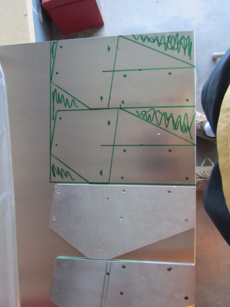
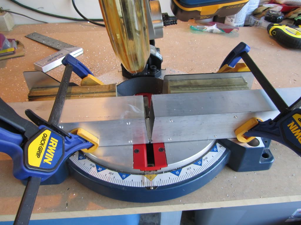
First, I marked and cut the V-cut in the keel, which allows the keel to bend up under the prop. I have to admit to a little "pucker factor" on this cut.... I just knew I was going to let the saw get away from me and ruin this metal that I've waited a long time for....

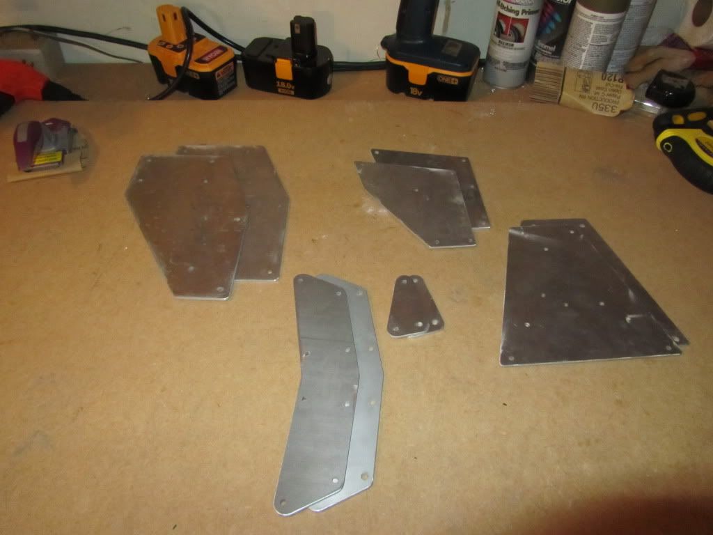
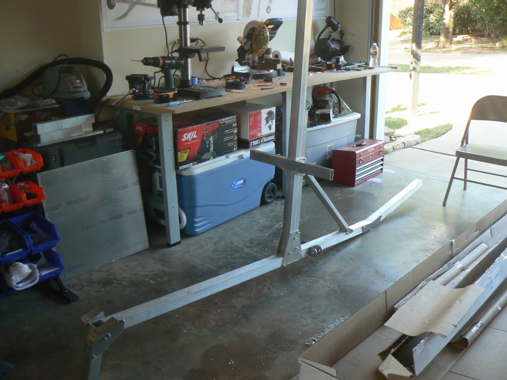
Here's the cut keel, ready for plates and bending....

IMG_2767.jpg


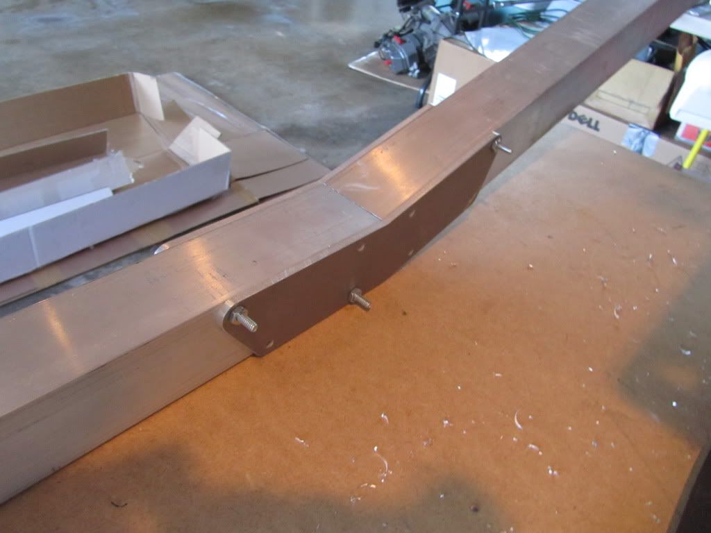
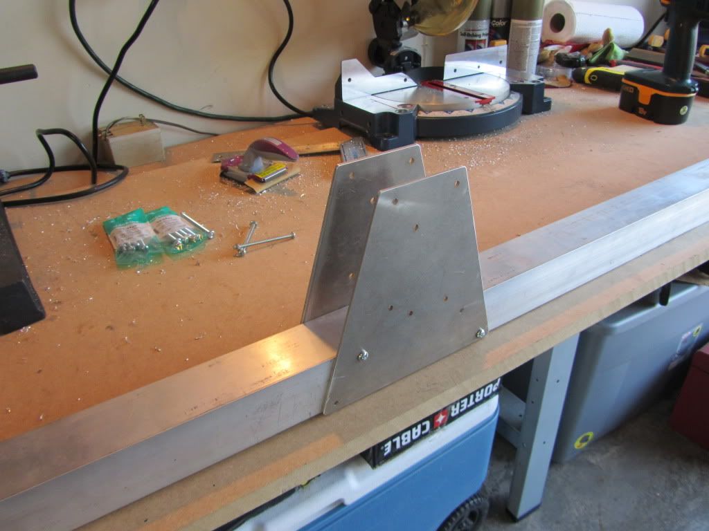
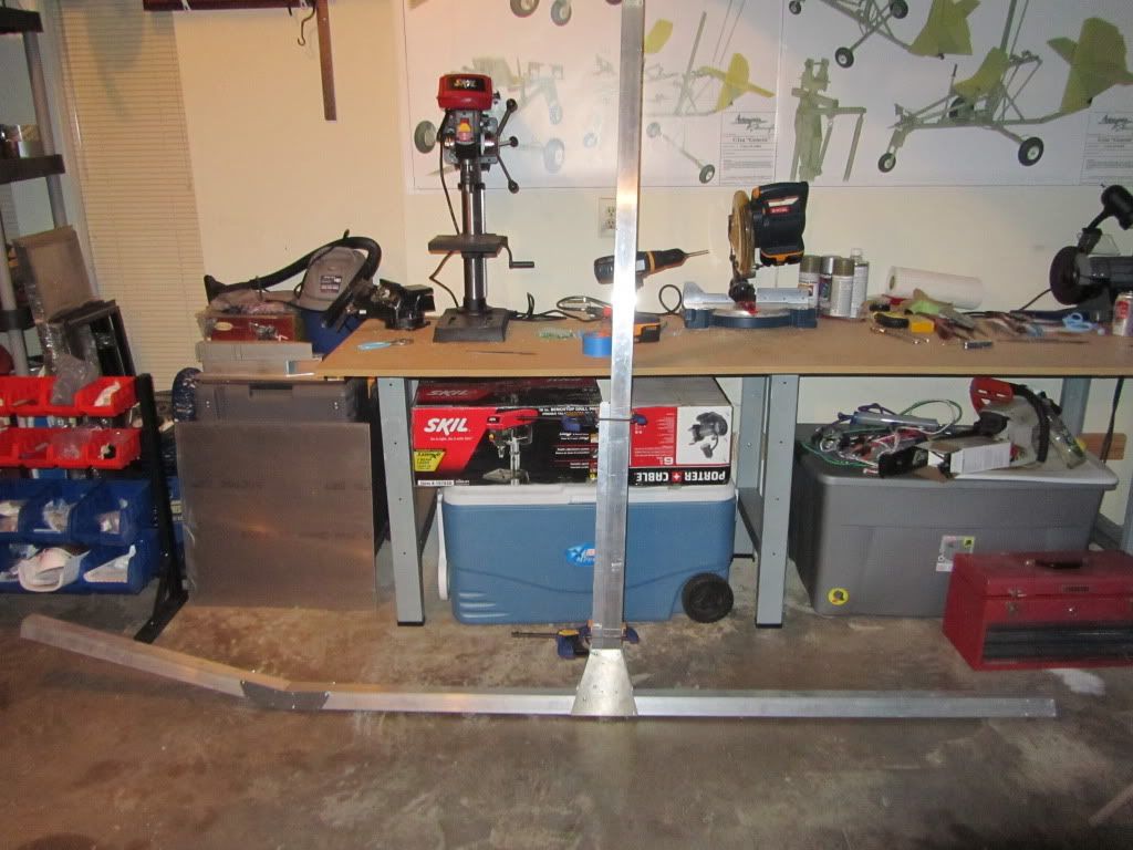
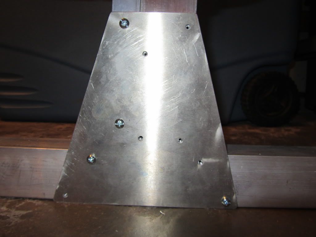
Here's the plates attached and keel bent up.... a very precision fit, thanks to Nicolas' pilot drilled plates and keel.

IMG_2770.jpg


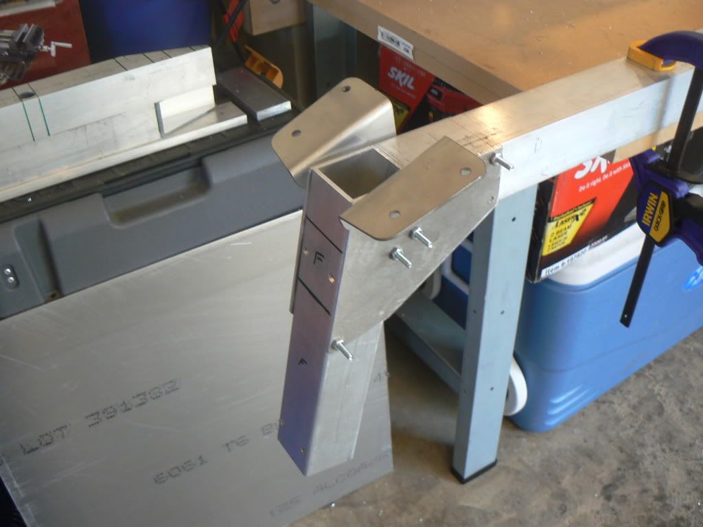
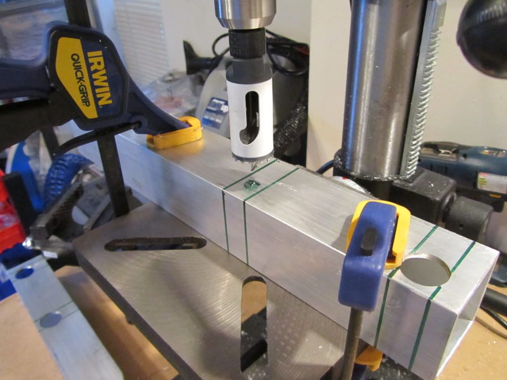
Next I moved on to the plates for attaching the mast and mast support tubes....

IMG_2771.jpg


Next I attached the mast support tube...

IMG_2775.jpg


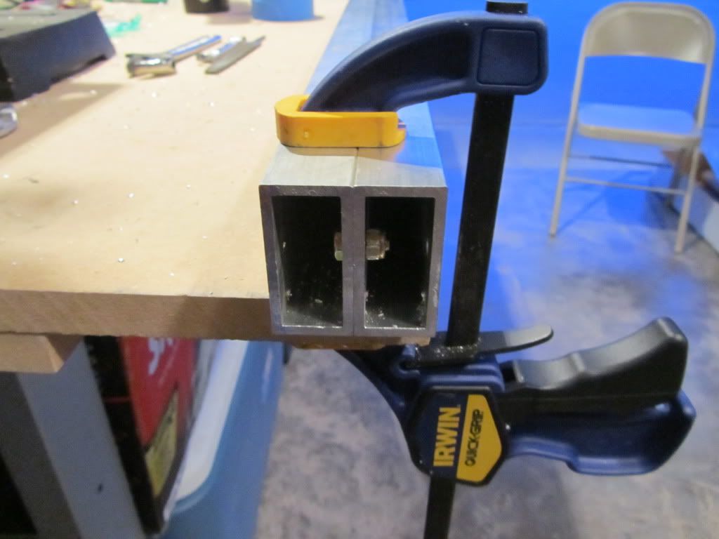
Then I moved on to building the mast.... the two 1x2 tubes must be bolted together with small bolts on the inside, making sure to keep proper alignment of the tubes...

Here's the bolting method, with one on each end....

IMG_2779.jpg


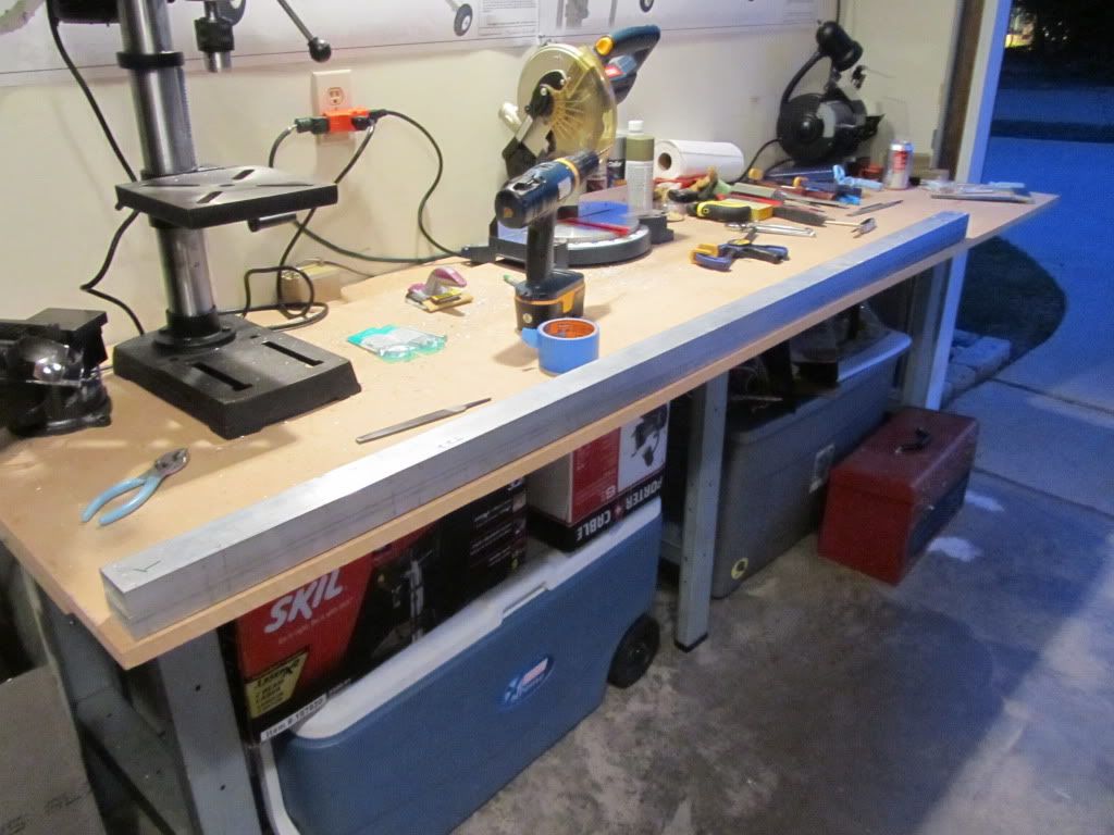
And the completed mast on the work bench.....

IMG_2781.jpg


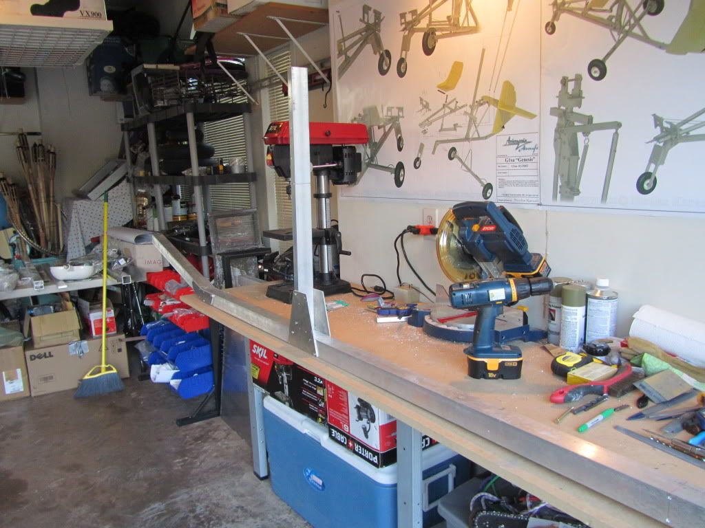
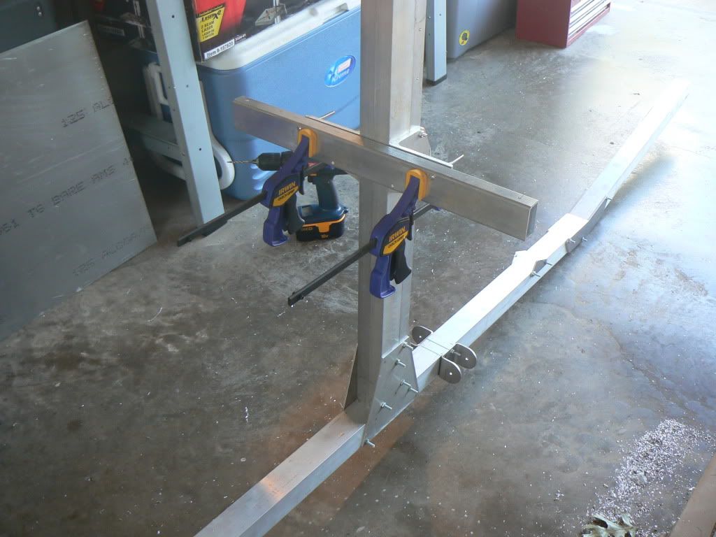
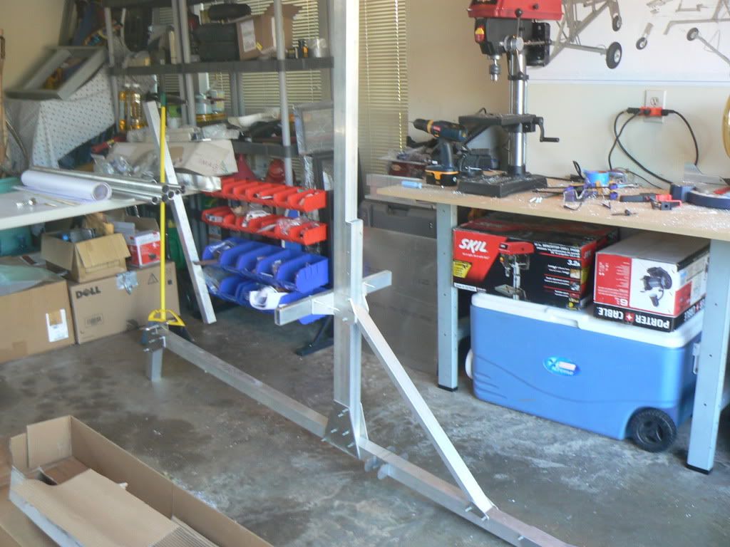
I then clamped the mast into position on the frame and checked for bolt hole alignement....

IMG_2787.jpg


Perfect alignment of all plate holes and pilot holes in the mast.... So far, everything has lined up perfectly, with no issues at all. I'm very pleased with the kit so far...

IMG_2783.jpg


On Saturday I will actually attach the mast and move forward with the rest of the frame..... no work for me on Friday, as we have friends throwing a high school graduation party for their daughter.
 
More Progress

More Progress

I got to work on the gyro on and off today....

I got the nose gear tubes and mounts done, the main gear attachments mounted, the mast bolted in, and some of the foundation for the round tubing mounts put in place.

Here's the nose gear area....

P1060740.jpg


Here you can see alot of the misc. plates and gear attach points that I mounted to the keel today...

P1060752.jpg


Here's the entire frame, in its current state...

P1060754.jpg


And the last one for today....

P1060755.jpg


With luck, I'll have the seat mounted and be able to sit in the gyro and make engine noises in a day or two.
 
Top