The Legacy of Martin Hollmann

Chèr Jean Claude,

this particular chart is from:
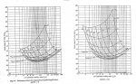
- naca advanced confidential report L4H07: "Charts for Estimation of the Charakteristics of a Helicopter Rotor in Forward Flight"

the same chart, albeit a bit cropped, can be found in :
- naca tn 716 "A Simplified Method of Determining the Charakteristiks of a Helicopter Rotor in Forward Flight"

In naca 716 the explanation of how the chart is derived is a bit better in my opinion.

I have zipped the two files since the naca report server is currently down (and will probably not be available for quite some time) . They are available here:
http://www.divshare.com/download/23949141-b78
 
Last edited:
Last pages of the book (MODERN GYROPLANE DESIGNS) Hollmann mentions all references.
 

Attachments

  • bt1.jpg
    bt1.jpg
    21.2 KB · Views: 6
naca 1998 does not seem to include the rotor lift/drag chart, at least not in the version I have. Also in my 1992 edition of "Modern Gyroplane Design" both naca L4H07 and 716 are not listed in the references. I have implemented the formulae of naca 716 in octave, the plot below is created with this program.
 

Attachments

  • ChartL4H07.png
    ChartL4H07.png
    32.3 KB · Views: 4
Thanks to Juergen and Giorgios
 
Can anyone tell me the origin of this figure used in "Martin's BumbleBee Design "?
Thank you.
These charts are also reproduced in Aerodynamics of the Helicopter by Gessow and Myers for P/L ratios between 0 and 0.6, JC.
 

Attachments

  • PL.jpg
    PL.jpg
    143 KB · Views: 0
I'm a bit surprised with the calculation presented in the NACA report L4H07.
According to the authors, P/L = (D/L)0 + (D/L)i + (D/L)p + (D/L)c with (D/L)i = CL/4. This induced drag ratio corresponds to a circular wing (ideal distribution of lift on the disc). But a rotor does not divide the pressure as a circular wing. The scanning by the blades produces a larger load near the lateral edges of the disc. This distribution is more akin to that of a square wing.
Would it not increase the induced drag by a "Oswald coefficient"? I think the error is not negligible in the example shown: 103 HP instead of 93 HP

 
Last edited:
If you assume (D/L)i differently it becomes inconsistent with Glauert's formula upon which simplified inflow calculation is based. If you want a better value for induced velocity use strip theory for the blade and integrate numerically.
 
Span load (blade load) is a different breed of cat than disc load, JC.

Span load averaged over the entire rotor disc will look similar to the round wing.

Di = Cl/4 seems to be etched in stone; every rotary wing text book I’ve ever seen uses that expression.
 
Span load averaged over the entire rotor disc will look similar to the round wing.
That is my point of disagreement, Chuck. Statistically, the disc rotor not have the same distribution. Distribution on the rotor disc is that shown by my previous schema. (I do not confuse them with the blades, of course)
Since (D/L)i = Cl /4 for a circular wing, it can not be the same for the broomed rotor
 
No integrate around the disc, Juergen. Drag opposes to the forward flight. Integrate transversally an edge of the disc to the other and you will see that the load of the rotor disk is not the same as a circular wing.
 
Last edited:
The full derivation is in naca 716 up to equation 25 roughly. The main point is that you have to stay consistent with Glauert's inflow calculation
 
Last edited:
Yes Chuck. They say: "Consider the rotor of a helicopter as a fixed airplane wing. Then, if it is assumed that the downwash is distributed uniformly across the rotor span..."
It seems to me this is not a affirmation but just a assumption to simplify. Is not it?
 
Yes of course it is, but at that time only analytical expressions could be used. Wind tunnel measurements show that the induced velocity has a very marked longitudinal distribution. Mangler and Squire developed a Fourier series expansion that is the best analytical solution available (as far as I know to the day). They showed that the induced velocity component of the flow field can be treated as a small perturbation and for that case the flow field satisfies Laplace second order differential equation. Using this series Bramwell showed ("Helicopter Dynamics" p. 137ff) that induced power is 11% higher than for the constant case. If the lateral distribution is to be modeled as well you have to take recourse to numerical methods, e.g. the flat wake theory www.rotaryforum.com/forum/showthread.php?t=36560 or to a full fledged 3D CFD solution.
One must keep in mind though that very successful Helicopters like the Flettner Fl-282 and the early Sikorsky types R-4B and S-51 have been designed using the assumption of a constant induced velocity.
 
Last edited:
Juergen, Glauert neglects too, the distribution on the disk span. This is what, in my opinion, gives a induced drag optimistic

 
Everybody knew that the assumption of constant induced velocity would give a value that was too low. An increase of 15% seems to have been the accepted figure but nobody really cared since the error in fuselage drag was even larger and the error introduced by blade flexibility was as about the same magnitude. That is why the analytical solutions for two per rev flapping angles a2 and b2, which were availabel even in the early thirties, were also neglected.

The last equation on your page is by the way a simplified longitudinal distribution of induced velocity.
 
Everybody knew that the assumption of constant induced velocity would give a value that was too low. .
Everybody did not know, Juergen, since Hollman does not take into account in its calculations. Power just about 10% optimistic. Thank you for your confirmation. Watching his calculations, I had a doubt on my spreadsheet
Also note that the longitudinal distribution (last equation) does not change the drag of the disk. Instead, the lateral distribution greatly influences the induced drag.
 
Last edited:
Don’t put too much faith in Hollmann’s calculations, JC. He was confused by simple vectors.
 
I only met the man once, at a conference in New York, knowing then nothing of his background or reputation. He was trying to sell the audience some theory he had cooked up that relied on achieving a vortex ring state in gyroplanes, and it seemed pretty bizarre to me. Ray Prouty was sitting near me, and when I asked him for his reaction, he was equally baffled by the whole thing.
 
Top