You are using an out of date browser. It may not display this or other websites correctly.
You should upgrade or use an alternative browser.
You should upgrade or use an alternative browser.
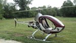
Streamlining my swashplate area- possibly?
- Thread starter StanFoster
- Start date
StanFoster
Active Member
- Joined
- Nov 16, 2003
- Messages
- 17,139
- Location
- Paxton, Il
- Aircraft
- Helicycle N360SF
- Total Flight Time
- 1250
Brett- The way I am struggling with the 0.032 aluminum....it may end up being butt ugly. Wow...but I am having fun.:yo:
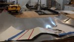
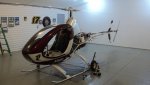
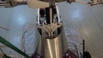
I replaced my pattern...and allowed extra on the rear, top and bottom. I will exactly trim it off to straight reference lines after it is fitted.
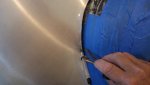
I duct taped spacer blocks around my pitch rods going to my swashplate. Eventually I will have brackets that will maintain this clearance.
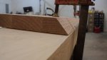
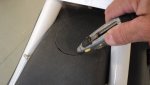
I have an outfeed roller for my table saw that got recommissioned as an aluminum roller. I slowly am rolling it into the desired curvature that meets my minimum clearances and has not unsightly kinks in it. The aluminum sheet came with a few minor dimples that I used a rubber hammer and cardboard on....and was able to iron out the imperfections. The one picture I am scribing to rough fit to the cabin...and will use a utility knife to score and then tear a nice edge that will be be smooth.
There is more to this than you think....just like any project.
Stan
Stan
I replaced my pattern...and allowed extra on the rear, top and bottom. I will exactly trim it off to straight reference lines after it is fitted.
I duct taped spacer blocks around my pitch rods going to my swashplate. Eventually I will have brackets that will maintain this clearance.
I have an outfeed roller for my table saw that got recommissioned as an aluminum roller. I slowly am rolling it into the desired curvature that meets my minimum clearances and has not unsightly kinks in it. The aluminum sheet came with a few minor dimples that I used a rubber hammer and cardboard on....and was able to iron out the imperfections. The one picture I am scribing to rough fit to the cabin...and will use a utility knife to score and then tear a nice edge that will be be smooth.
There is more to this than you think....just like any project.
Stan
Stan
Attachments

StanFoster
Active Member
- Joined
- Nov 16, 2003
- Messages
- 17,139
- Location
- Paxton, Il
- Aircraft
- Helicycle N360SF
- Total Flight Time
- 1250
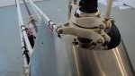
Brett- I was going to wrap the rear edges around a rod....but....this 0.032 is plenty stiff enough. I may consider just rolling the edge back on itself. I tried a scrap piece and the edge looks nice rolled over.
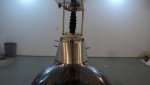
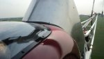
I have it fitting the cabin ...and used a laser to mark the top nice and level....the rear sloping edges and the bottom sloping edges are all cut and symmetrical with each other. I have to put it back on the roller, then peen out some blemishes.
If you look on the last picture...there is a slight concave depression ......my excuse is that I am not done with it yet!
It just looks smoother for the aiflow to me.
Attachments
WHY
Gold Member
- Joined
- Jun 13, 2005
- Messages
- 4,384
- Location
- miami,oklahoma
- Aircraft
- Ercoupe and Cessna 150, 152, 172, 140, Aeronca,7ac, Citabria,Chief,Piper PA11,PA12
- Total Flight Time
- 215
Stan
If this thing gets any better you are going to have to re-name it the "rotary orgasam"
Tony
If this thing gets any better you are going to have to re-name it the "rotary orgasam"
Tony
GaryMac
Member
- Joined
- Sep 3, 2008
- Messages
- 814
- Location
- Colleyville, TX
- Aircraft
- Building a Genesis G1sa
- Total Flight Time
- 14
Looking good, Stan.
I was worried for a while, but now that I see you are using duct tape, I know that you have the proper tools for the job, and everything will turn out just fine.
I was worried for a while, but now that I see you are using duct tape, I know that you have the proper tools for the job, and everything will turn out just fine.
StanFoster
Active Member
- Joined
- Nov 16, 2003
- Messages
- 17,139
- Location
- Paxton, Il
- Aircraft
- Helicycle N360SF
- Total Flight Time
- 1250
Gary- I replaced the duct tape with clecoes!
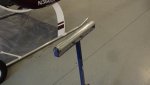
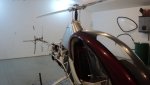
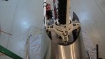
Here are some more progress pictures. I rolled the rear edge of the 0.032 aluminum by making a poor mans brake. Basically just some hardwood with a 45 degree sharp edge....sandwiched across another hardwood that has square corners.
I simply let 1/4 inch protrude past the bevel...and peen it over with a many small taps with a hammer and a block of wood. Once there is a clean 45 degree bend....I take the beveled wood out and finish folding the aluminum ovedr. It leaves a much nice edge that is stiffer....and just better looking.
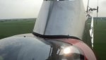
I rolled over the sloping rear edges...and the very bottom edge of this fairing.
I changed my design at the top.....I had 3/8 inch of clearance around my pitch rods....but decided to lower the top.....but pull it in tighter. So even though I am exposing more of the lower swashplate to the airflow....the fairing could now be made about 3/4" narrower, so I believe the extra drag that the lower swashplate now has....will be offset by the fairing being narrower and passing under it. Another bonus is I can easily check my rodends now as usual.
I am waiting on more rivets and some rubber channel that will fit the serpentine cutout for the cabin. I should have this ready for my painter after July 4th.
Here are some more progress pictures. I rolled the rear edge of the 0.032 aluminum by making a poor mans brake. Basically just some hardwood with a 45 degree sharp edge....sandwiched across another hardwood that has square corners.
I simply let 1/4 inch protrude past the bevel...and peen it over with a many small taps with a hammer and a block of wood. Once there is a clean 45 degree bend....I take the beveled wood out and finish folding the aluminum ovedr. It leaves a much nice edge that is stiffer....and just better looking.
I rolled over the sloping rear edges...and the very bottom edge of this fairing.
I changed my design at the top.....I had 3/8 inch of clearance around my pitch rods....but decided to lower the top.....but pull it in tighter. So even though I am exposing more of the lower swashplate to the airflow....the fairing could now be made about 3/4" narrower, so I believe the extra drag that the lower swashplate now has....will be offset by the fairing being narrower and passing under it. Another bonus is I can easily check my rodends now as usual.
I am waiting on more rivets and some rubber channel that will fit the serpentine cutout for the cabin. I should have this ready for my painter after July 4th.
Attachments

StanFoster
Active Member
- Joined
- Nov 16, 2003
- Messages
- 17,139
- Location
- Paxton, Il
- Aircraft
- Helicycle N360SF
- Total Flight Time
- 1250
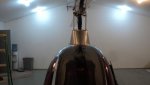
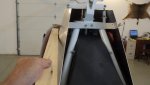
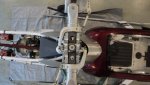
Last pictures.....the fairing is all clecoed on now, no duct tape. 
All that is left to do is iron out some wrinkles....install some nut plates where each clecoe is......sand it and take it to the painter next week.
There will be a small rubber channel bonded on where the fairing meets the cabin to finish that off. I will then be able to easily open either side and swing out the fairing for any inspecting I want to do.
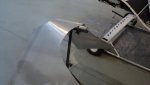
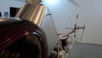
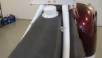
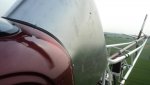
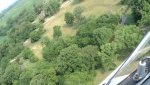
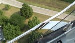
Vance- The last picture is especially for you. I placed a straight board along side the fairing so you could get a feel how the fairing has a nice curve and gently pulls the airstream back in. I have the option of making the fairing come in even tighter at the rear by simply working a larger bend into the alumnum. I know there is only so much the air can suck in before becoming unhappy and turbulent. What is your expert opinion on my tail end as far as the flare in. Need a little more? or do you think its about right?
Anyone that can go as fast as you on a motorcycle has to have a good aerodynamic eye.
In my opinion....not even talking about the wiffle ball stuff at the top that has to have less drag now....but the bottom half just looks like the air will be happier going along that aluminum skin and having some tuck in at the back....than the way the fuel tank was.
Nothing like a flight test.
Stan
Stan
All that is left to do is iron out some wrinkles....install some nut plates where each clecoe is......sand it and take it to the painter next week.
There will be a small rubber channel bonded on where the fairing meets the cabin to finish that off. I will then be able to easily open either side and swing out the fairing for any inspecting I want to do.
Vance- The last picture is especially for you. I placed a straight board along side the fairing so you could get a feel how the fairing has a nice curve and gently pulls the airstream back in. I have the option of making the fairing come in even tighter at the rear by simply working a larger bend into the alumnum. I know there is only so much the air can suck in before becoming unhappy and turbulent. What is your expert opinion on my tail end as far as the flare in. Need a little more? or do you think its about right?
Anyone that can go as fast as you on a motorcycle has to have a good aerodynamic eye.
In my opinion....not even talking about the wiffle ball stuff at the top that has to have less drag now....but the bottom half just looks like the air will be happier going along that aluminum skin and having some tuck in at the back....than the way the fuel tank was.
Nothing like a flight test.
Stan
Stan
Attachments
gyrodeputy
Newbie
Flight Test
Flight Test
Hi Stan,
The new cover looks great! Just a question. Are you gonna flight test it before you pay to have it painted?
Stay safe and thanks for all your sharing!
Flight Test
Hi Stan,
The new cover looks great! Just a question. Are you gonna flight test it before you pay to have it painted?
Stay safe and thanks for all your sharing!
StanFoster
Active Member
- Joined
- Nov 16, 2003
- Messages
- 17,139
- Location
- Paxton, Il
- Aircraft
- Helicycle N360SF
- Total Flight Time
- 1250
Heath- i have my nutplates to put on, then yes, i will flight test it. My painter said he can get it painted in a few days. My flight test next week in these high temps will be giving me too generous of groundspeed figures. I will reduce the speeds according to density altitude. Stan
baronpilot
Newbie
- Joined
- Apr 17, 2012
- Messages
- 544
- Location
- Auburn, IN
- Aircraft
- Baron B55, Bonanza V35, Brantly B2B
- Total Flight Time
- 2500
Stan,
Very nice work. There is no chance of this fairing bending in and binding up the swashplate mechanism, correct?
Very nice work. There is no chance of this fairing bending in and binding up the swashplate mechanism, correct?
StanFoster
Active Member
- Joined
- Nov 16, 2003
- Messages
- 17,139
- Location
- Paxton, Il
- Aircraft
- Helicycle N360SF
- Total Flight Time
- 1250
Todd- You ask the same question I did myself! This thing is solid. I can push in on the nose and its not going anywhere. There are 10 attachment points on it. I have aluminum angles riveted with 3/16 inch steel rivets. Overkill in my opinion! If you study the latest pictures, I cut it down about 1.25 inches so as to completely be under the left/right/for/aft tilt of the swashplate. I was able to make it narrower at the top doing this. My nutplates should be here Friday, and I have Saturday morning to button it up. We are having 2 grandkids over thru Monday, and they come first in my life. But after I am done playing with them, looks like I will be flight testing on Tuesday or the 4th. Yee hah! Stan
choppergabor
Newbie
- Joined
- Apr 15, 2009
- Messages
- 4,864
- Location
- Sunshine State
- Aircraft
- N65GK Behemoth
- Total Flight Time
- Too few to mention
What's a density altitude? Looks good my brotha. I am sure the reduced drag will please your anti parasite drag mentality. Nice and slowly you'll have enough improvement done on it and will eventually run out of things to do! Than what?
Looks good my brotha. I am sure the reduced drag will please your anti parasite drag mentality. Nice and slowly you'll have enough improvement done on it and will eventually run out of things to do! Than what? StanFoster
Active Member
- Joined
- Nov 16, 2003
- Messages
- 17,139
- Location
- Paxton, Il
- Aircraft
- Helicycle N360SF
- Total Flight Time
- 1250
Gabor- Probably will be tinkering for some time. Its a genetic defeect I have! Stan
500e
Active Member
- Joined
- Jul 13, 2008
- Messages
- 552
- Location
- UK
- Aircraft
- 500c\d\e 300C & CBi
- Total Flight Time
- a lot more now
Wondered why you cut it down, personally I don't think it would have been a problem, especially with a folded\rolled edge, or taken higher & formed into a vertical, the forming would have stiffened the structure.
But it looks the business along with the rest of the build as perfect as man can make,.
I am an inspector for our national motor sport body & although most of the cars we see are good, there is always one that stands out :first:
But it looks the business along with the rest of the build as perfect as man can make,.
I am an inspector for our national motor sport body & although most of the cars we see are good, there is always one that stands out :first:
StanFoster
Active Member
- Joined
- Nov 16, 2003
- Messages
- 17,139
- Location
- Paxton, Il
- Aircraft
- Helicycle N360SF
- Total Flight Time
- 1250
500e- I cut it down to remove all possibility of it jambing my control rods. Say for instance that Red Tailed hawk that lives in my Chopper Channel and I have come close to him twice...or the Canadian geese that are all over flying low around..........one of these hits my swashplate fairing ....then I could see the bird mashing my fairing in and "possibly" interferring with my control of the lower swashplate. Now that I lowered it 1.25 inches...it wont. I feel that lowering it also allowed me to make it narrower so as not to have to clear the lower stationary swashplate star. So, even though I am exposing just a little more to the airflow on top....I have narrowed the cross section of the fairing to make up for that.
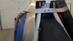
In post #85....the fourth picture from the rear showing the inside of the fairing..........I have a thick flat aluminum spreader bar bolted to my hood of the frame. This keeps the sides where they should be ....away from the control rods. I wanted to make it where you could lean against it and not move it. Its unbelievable how when you attach an object at just a few points not in the same plane.....3d in other words...how strong it is. Its like my curved stair railings. I only need to attach them at the top and bottom as its held in two different planes....but a straight stairway needs a newel post midway because its anchored only in one plane.
Hey.,..I may be all wrong being extra cautious...but I would rather error on the caution side!
Stan
Last edited:
All_In
Gold Supporter
- Joined
- Apr 21, 2008
- Messages
- 16,105
- Location
- San Diego, CA. USA
- Aircraft
- Airgyro AG915 Centurian, Aviomania G1sb
- Total Flight Time
- Gyroplane 70Hrs, not sure over 10,000+ logged FW, 260+ ultralights, sailplane, hang-gliders
Brother Stan
This really did come out so well.
Most excellent Job... cannot wait for the flight tests and to see her painted.
PS:
Don't be breaking any pattern speed limits?????!!!!
This really did come out so well.
Most excellent Job... cannot wait for the flight tests and to see her painted.
PS:
Don't be breaking any pattern speed limits?????!!!!
Last edited:
StanFoster
Active Member
- Joined
- Nov 16, 2003
- Messages
- 17,139
- Location
- Paxton, Il
- Aircraft
- Helicycle N360SF
- Total Flight Time
- 1250
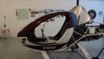
My nutplates arrived yesterday and I couldnt get out to my shop early enough this morning. They are all installed and my fairing is on ready for flight testing. I put a rubber seal where it intersects the cabin. Just testing it for this final fit.
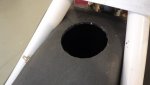
I also had a small dilema. My fuel filler cap. I first was going to cut an access hole in the right side of my fairing...but I kept stopping myself from doing that. My 2nd choice was to have a hole with a round cover plate that I would remove a screw and swing it out for filling. I didnt like that either.
I then decided to just unscrew the right side....4 screws...each time I filled it, knowing I would get tired of that.
My best solution just hit me. Cut a new filler hole in the middle inside the fairing. Problem with that was finding the right apparatus. I went down to my local Menards Helicopter Supply store and checked out their plumbing section. I ended up buying a pvc toilet flange....and found a threaded nipple and neat cap that would make a perfect gas cap. Trouble is I had to turn it down to be able to bond it to the toilet flange. I used my sophisticated lather.....a 12 inch bench disc sander...:first: and turned it down till it was a tight fit...then bonded it . The toilet flange was also turned down on my miter box by cutting about 48 facets around its outer edge...then sanding it down. Perfect! By the way, I soaked this pvc in kerosene for days....and still have my sample soaking. Cant tell a bit of softening....and this filler cap wont ever be sitting in fuel anyway.
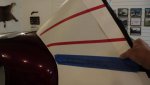
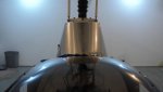
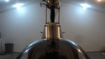
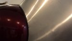
The last pictures are the fairing with the rubber seal on my cabin..and some overhead shots so you can get the feel of the streamling action. Notice the rear wings gently curve the airflow in. I cant wait to see how she performs.
My grandkids are coming over...so flight testing may not be till next week.
After that.....the fairing comes off and all minor surface refections will be ironed out as best as I can...then finished with a random orbit sander and then off to my painters. Just like my landing gear fairings....I have a distinctive burgundy/white color scheme that compliments the aesthetics of the rest of the ships paint job.
I am considering putting a small brace at the top rear of the fairing to keep them from possible vibrating. Plus...there will be some of that weathestripping bonded on the very top oval cutout.
Stan
I also had a small dilema. My fuel filler cap. I first was going to cut an access hole in the right side of my fairing...but I kept stopping myself from doing that. My 2nd choice was to have a hole with a round cover plate that I would remove a screw and swing it out for filling. I didnt like that either.
I then decided to just unscrew the right side....4 screws...each time I filled it, knowing I would get tired of that.
My best solution just hit me. Cut a new filler hole in the middle inside the fairing. Problem with that was finding the right apparatus. I went down to my local Menards Helicopter Supply store and checked out their plumbing section. I ended up buying a pvc toilet flange....and found a threaded nipple and neat cap that would make a perfect gas cap. Trouble is I had to turn it down to be able to bond it to the toilet flange. I used my sophisticated lather.....a 12 inch bench disc sander...:first: and turned it down till it was a tight fit...then bonded it . The toilet flange was also turned down on my miter box by cutting about 48 facets around its outer edge...then sanding it down. Perfect! By the way, I soaked this pvc in kerosene for days....and still have my sample soaking. Cant tell a bit of softening....and this filler cap wont ever be sitting in fuel anyway.
The last pictures are the fairing with the rubber seal on my cabin..and some overhead shots so you can get the feel of the streamling action. Notice the rear wings gently curve the airflow in. I cant wait to see how she performs.
My grandkids are coming over...so flight testing may not be till next week.
After that.....the fairing comes off and all minor surface refections will be ironed out as best as I can...then finished with a random orbit sander and then off to my painters. Just like my landing gear fairings....I have a distinctive burgundy/white color scheme that compliments the aesthetics of the rest of the ships paint job.
I am considering putting a small brace at the top rear of the fairing to keep them from possible vibrating. Plus...there will be some of that weathestripping bonded on the very top oval cutout.
Stan
Attachments
StanFoster
Active Member
- Joined
- Nov 16, 2003
- Messages
- 17,139
- Location
- Paxton, Il
- Aircraft
- Helicycle N360SF
- Total Flight Time
- 1250
first test flight----she is definitely faster!
first test flight----she is definitely faster!
I had time to make a test flight on my swashplate fairing. I flew at gradually increasing speeds trying to see if I was getting unusualy turbulence to my tail rotor. It felt like it was on rails. I wasnt mentally prepared for an all out test....I just wanted full concentration on any different control feel, noise...vibrations etc....instead of doing some 180 degree speed runs.
BUT------
I can honestly say this ship is faster! It slips past 100 much easier with the landing gear fairings....and there is no doubt its even easier with this swashplate fairing.
I wasnt intending on doing an accurate speed run as the density altitude is around 2500....and I will wait till its down to the DA I had recorded all my speeds prior at. I can mathematically convert...but I just would rather wait till its the same DA, and I am fully comfortable with the handling of this fairing.
But....there is no doubt it is faster. I had my ASI reading higher than it ever has before while holding exactly 15 degrees of collective. It was buried at 120 mph. 116-117 was the highest I had ever seen it. But...I go buy averaged GPS groundspeeds as these are dead on accurate. I noticed it has less rumbling sound in my opinion.....
Its definitely a green light to get this fairing off to my painter next week.
I have a fly-in to go to on the 14th and this fairing will be burgundy/white and installed by then.
I will then do some very accurate speed runs and just see how the numbers at different collective pitch settings compare. I know my initial goal of gaining 2 mph has more than been exceeded.
Man....this stuff is a lot of fun.
Stan
Attachments
choppergabor
Newbie
- Joined
- Apr 15, 2009
- Messages
- 4,864
- Location
- Sunshine State
- Aircraft
- N65GK Behemoth
- Total Flight Time
- Too few to mention
Another piece of efficiency and aesthetic combo for the super tweaked Turbinator. Life's good. I am glad things are turning out well for you and the tests are confirming the theories It is always nice to be proven right!
It is always nice to be proven right!