Simulation Program for Rotary Wing Aircraft RotaryWingSim 2.0

kolibri282

Super Member
Joined
Aug 2, 2009
Messages
3,054
Location
Duesseldorf
This thread has been opened as a place to discuss questions related to RotaryWingSim the simulation program for rotary wing aircraft which is available in the link below. Please do not post to the distribution thread in the "Technical Books, Papers and Publications" section. Please note that due to personal circumstances I currently do not have much time and therefore there might be a considerable delay befor I get around to answering any questions. This includes the fact that the separate documentation package mentioned in the user guide will not be available before sometime in June.

In the month to come I will try to compile some more information on how to use the program and guide you through example calculations.

RotaryWingSim is available here:
https://www.rotaryforum.com/forum/r...am-for-rotary-wing-aircraft-rotarywingsim-2-0
 
Last edited:
Juergen,
Mes compétences en informatique sont hélas insuffisantes pour ouvrir votre simulateur.
Peut-être pourriez-vous m'indiquer vos résultats dans les conditions ci-après, pour comparaison avec le mien?
Portance: 2124 N à 30m/s en atmosphère 1,22 kg/m3, avec:
rotor 6,3m x 0,18m 2 pales rectangulaires, 7,4 kg/pale uniformément répartis.
profil: Cx0 = 0,011 et Cz max = 1,3 Ligne de portance nulle calée à +3,5°.

Mon simulateur Excel m'a donné pour 30 m/s:
Régime stabilisé: 419 t/mn
Incidence disque: 8,47°
Trainée moyenne rotor: 316 N
Battement longitudinal: 2,50°
Battement transversal: 1,22° pour une conicité de 3°
Vibration axiale sur le moyeu: 39 N Sin(2ωt) (si pales supposées libres en battement)
Vibration radiale: 62 N tournant à 2ω (si pales supposées rigides en trainée)
Descente verticale: 394 t/mn, -8,26 m/s

Merci
Jean Claude
 
Last edited:
Chèr Jean Claude,

vous trouvez si dessous attaché un résumé bref de mes résultats pour
une petite selection des valeurs d`entrée. Votre liste de valeurs
ne contient pas le facteur de perte du bout de pale (tip loss factor).
J'ai alors fait des calcules utilisant des valuers de 1.0 et 0.97.
Presque tous les rapports naca utilisent le dernier, 0.97. On voit que
l'influence de cette valeur est assez important. J'ai aussi essayé
de trouver un valuer de facteur de trainee du profil pour un facteur
de perte du bout de pale de 1.0 qui donne la meme vitesse der rotation
et cet valuer est de 0.13.

Vous trouvez en plus un fichier zip avec des listes de resultats compréhensif
en cas que vouz aimriez faire une analyse plus détallié. Le guide d'utilisation
de RotaryWingSim contien une bref explication des valuers.

Merci pour fournir les resultats the vos calcules, ca donne une
bonne chance de validation de mon logiciel

Les resultats sont:

Régime stabilisé: N
Incidence disque: alfaD
Battement longitudinal: a1
Battement transversal: b1
 

Attachments

  • Resultats_JC_1.png
    Resultats_JC_1.png
    24.7 KB · Views: 1
  • Bensen_jc.zip
    18.7 KB · Views: 0
Last edited:
Thank you Juergen,
I do not understand where you got your drag coefficient profile. It is 0.011 instead of 0.11, right?

My simulation takes into account the tip loss: Arbitrarily, cL is halved from R - 1 chord and cD profile is kept the same.
 
You are right, it is 0.011, thanks for pointing this out. I have noticed that the formulae I am using seem to result in a smaller disk angle. I am currently trying to reproduce the values from another report "An Investigation of the Longitudinal Stability of an Autogyro". I had to increase the drag coefficient from 0.0165 to 0.0192 to get the same inflow angles, this is one point to investigate. Part of the problem might be that I am using the usual three term drag polar instead of a single valued one. A complete derivation of the formulae is in naca 716 and 487. The integration procedure sets cL to zero from r/R=.97. Since lift is highly nonlinear the result might be different from the one you get when using cL=0.5*cL for the outer portion of the blade, though I have not checked this.
 
Last edited:
Juergen,
From my side, cd min of blade section is simply that given the JavaFoil with reasonable transition from laminar to turbulent at 0.15 chord. So, cd about 0.010 for 8H12 at Re = 1,500,000
Added to this is the induced drag coefficient cL ^ 2 / Pi.A (A is the aspect ratio of the blade)
Only then, these blades rotate in a general air flow deflected by the general lift produced.
 
But cD is not constant with angle of attack, that is why the naca folks introduced the three term drag polar. Since calculating the inflow angle for zero torque modifies the angle of attack the three term drag polar should give a better approximation.
 
But cD is not constant with angle of attack,
You are right Juergen,
However, this is largely due to the displacement of the transition point of the boundary layer. In the turbulent atmosphere of a rotor, it seems to me more accurate to enter a constant value, than evolutive coefficient established in an unrealistic laminar flow . This rigor is unfortunately illusory.
Below, right, my simulation with cD = 0.010 (red points) compared to flight manual Robinson R22.


Also, the cL slope is assumed to be constant, although it improves with Mach number. But 5,7/ rad with infinite span seems a reasonable mean.
 
Last edited:
It seems to me that the use of power laws for the rotor drag is perhaps not just an attempt to capture the measured two dimensional flow values. In the report below a cubic law is used to also cover stall and the report states that only the use of this law reveals a possible source of instability. If a constant value is used it might be difficult to find the right one since one would have to guess what the overall influence of various effects might be to come up with a constant value that covers these effects.
http://naca.central.cranfield.ac.uk/reports/1949/naca-tn-1906.pdf
 
Juergen,
What we need to know is the drag and rpm by using a profile (for example 8H12). If nobody knows what curve gives in the environment disrupted of a rotor, then how to know the delta coefficients?
This rigor of the cubic law before the stall is amazing given the oversimplification above stall: According TN 1906, cL and cD assumed constant (cL= 0,60 cD= 0,25) But we know that this is far from being like that. It's like here:


Unstability of autorotation: It comes from the increase of drag in all stalled area (the cD jump to 0.25 and much more, in fact). It seems to me the cubic term has little effect across from here.

In my spreadsheet, for the vertical descent, if
W = 2700 lbs, R = 20 ft, c = 1.87 ft (2 blades), θ = 4°, no twisted,
cD = 0.0087 before stall and cD = 2 Sin²(i) above, max cL = 1,2 and cL = 2 . Sin (i) . cos (i) above (as shown by this typical curve),

then 193 r.p.m and Vv: 32 ft/s balances the torque and the weight.


The instability appears when θ = 7° (unstable balance to 162 r.p.m)

 
Last edited:
What we need to know is the drag and rpm by using a profil

Dear Jean Claude,

since we do not have our own wind tunnel the only way, in my opinion, to improve our simulation results is to compare them against measured data
This is one of reasons why I wrote my program. Some time ago I have calculated some data points from naca 434 for the PCA-2 autogyro. In the zip
file you will find the input file for the aircraft (PCA2ps.dat) two input files for the flight state (*.flt) and two result files (*.lis) and a spread sheet for
convinient data comparison. Perhaps you could also calculate the data points A6-3 and A6-5 of the report so that we can compare results.
By the way I think vertical descent is not the best regime for comparison due to the uncertainty of the inflow state.


Since you have posted a link to the report I take it you already downloaded it:
http://www.rotaryforum.com/forum/showthread.php?t=32483
 

Attachments

  • PCA021913Snap2035.zip
    50.1 KB · Views: 0
Juergen,
It is complicated to me to compare my calculation results with in-flight measurements of PCA 2 because:
- The fixed-wing relieves the rotor in unknown proportions depending on the angle of horizontal empenage.
- The fixed-wing relieves the rotor in unknown proportions depending on the angle of air stream under the rotor.
- The rotor blades twists, when changes rpm (according report 515)
- My spreadsheet is set for 2 blades, and I should change it for 4 blades (The same solidity factor changes the aspect ratio of the blades.
- My spreadsheet is set for constant chord , and I should change it for PCA2 chord .
- My spreadsheet neglects radial flow on the blades: High Mu and low aspect ratio are outside its domain.

Comparison with Robinson R22, which I have already given you, do not have these drawbacks. What gives your simulation in this case?
 
Last edited:
Dear Jean-Claude,

helicopter data are, unfortunately, not helpful in developing a numerical model for autogyros. All the papers concerned with flight stability state that the behaviour of a powered rotor is very different from that of an unpowered (auto rotating) one. Therefore the R-22 Date are pretty useless for developing an autogyro simulation model. I am also not aware of any data recorded in test flights for the R-22. Only real test data allow you to asses how well a mathematical model describes autogyro physics. Data including wing/rotor lift distribution are available, eg in:
naca-tr-523 The Influence Of Wing Setting On The Wing Load And Rotor Speed Of A PCA-2 Autogyro as Determined in flight

or:

naca-tr-475 Wing Pressure Distribution and Rotor Blade Motion of an Autogiro as Determined in Flight

If your spread sheet does not allow you to take these influences into account you could include the data from these reports into your calculation.
 
Last edited:
helicopter data are, unfortunately, not helpful in developing a numerical model for autogyros.
Juergen,
My spreadsheet is only based on the simple aerodynamic laws of a profile and cyclical changes resulting from slipped circular motion. Helicopter or gyroplane not change anything. Just A.o.A disk is different.
Autorotation comes from the AoA disk for cancellation of the torque on the shaft, and a sufficient lift.
Helicopter comes from the pitch setting of blades for sufficient lift.
Anything else. No specific law is required for one or other.

Inapplicable to the old gyroplanes to high solidity ratio of rotor, because their surface is almost enough to lift the weight without rotation (high mu).

 
Last edited:
Only real test data allow you to asses how well a mathematical model describes autogyro physics.
naca-tr-475 Wing Pressure Distribution and Rotor Blade Motion of an Autogiro as Determined in Flight
Juergen, here is my comparison between the results given by my spreadsheet and flight tests on PCA2.

Rotor characteristics:


Mass: 79 lbs each blade,
Symmetrical profile Gö 429
Dynamic twisting 0.89° at tip per 1000 pounds of load (according NACA report 515),

Data entered in spreadsheet :
It is designed for two-bladed rotors, but four blades can be simulated as two nested two-bladed rotors sharing the load, with the induced velocity twice that of the isolated two-bladed rotor.

Drag blade profile is about cD0 = 0.010 at this Reynolds number, but here cD0 will be assumed 0.012, because it is increased by the inter-blade cables, shrouds, and other protuberances.


The comparison focuses on the glide conditions at μ= 0.2 and 0.35
Rotor load is assumed about 88% at μ = 0.2 and 80% at μ = 0.35 because the fix-wing, according the NACA report 475:


If the total load in glide is 2930 pounds (weight), then the rotor load is only 2578 lbs (5680 N each “two bladed rotor”) at μ = 0,2
With this load, the blade pitch is modified by the dynamic twisting:


The chord of parts 1,2,3,4 and 11 have also been corrected.


My results:


At 0,0676 lb/cubic.ft and 46.9 mph during glide (43.8 mph indicated), rotor thrust = 2 x 5692 N requires disk angle = 13,4° So, rotor drag = 2 x1319 N, 142 rpm, a1 = 2,19°, b1 = 2,74° if coning = 6,8°, cL disk = 0,32 and cD disk = 0,076

With μ= 0,35 the rotor load is 80% If the total load in glide is 2930 pounds (weight), then the rotor load is 2344 lbs (5174 N each “two bladed rotor”)


At 0,0676 lb/cubic.ft and 83.2 mph true during glide (78 mph indicated), PCA 2 rotor thrust = 2 x 5200N requires disk angle = 7.3° So, rotor drag = 2 x 658 N, 147 rpm, a1 = 3.6°, b1 = 3.1° (if coning = 6,1°), cL disk = 0,095 and cD disk = 0,012 (ratio L/D = 7.8)

Forecasts are valid to low μ, but in my mind r.r.p.m differences becomes great to the high μ, because the radial flow has been neglected in these calculations:


Unfortunately John B. Wheatley himself points out an inconsistency in the measurements of the data used (NACA report 523):

 
Last edited:
Cher Jean Claude, it's great that you have been able to use the data from the various reports for your calculations. I will be able to come up with results for the two mu values in about two weeks.

Thanks,

Jürgen
 
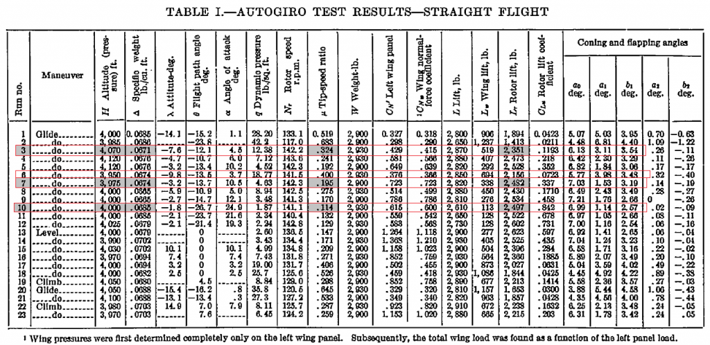
Juergen, Voici d'autres résultats de mon tableur comparés aux mesures en vol sur l’autogire Pitcairn PCA 2 .[/B]
Les comparaisons ont porté sur les vols planés n° 3, 7, 10 et 6 du rapport NACA 475, effectués en vols planés (pas d'effet du souffle de l’hélice sur l’aile fixe)


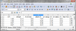
Résultat pour les données correspondantes au vol plané n° 10
Le régime calculé du rotor dans ces conditions de charge et de pression dynamique et de masse volumique est 142 t/mn, tandis que la mesure a donné 141,1 t/mn
L’angle d’attaque calculé du disque est 27,2°, tandis que la mesure a donné 24,9° (arbre) + 1,14° (a1) = 26,0°
L’angle de battement longitudinal a1 calculé est 1,3° tandis que la mesure a donné 1,14°
L’angle de battement transversal b1 calculé est 2.6° tandis que la mesure a donné 2.6°

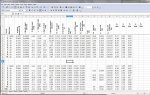
Résultat pour les données correspondantes au vol plané n° 7
Le régime calculé du rotor dans ces conditions de charge et de pression dynamique et de masse volumique est 142 t/mn, tandis que la mesure a donné 142,3 t/mn
L’angle d’attaque calculé du disque est 13.8°, tandis que la mesure a donné 10,5° (arbre) + 1,53° (a1) = 12°
L’angle de battement longitudinal a1 calculé est 2.1° tandis que la mesure a donné 1,53°
L’angle de battement transversal b1 calculé est 2.8° tandis que la mesure a donné 3.2°

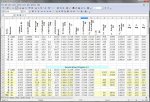
Résultat pour les données correspondantes au vol plané n° 3
Le régime calculé du rotor dans ces conditions de charge et de pression dynamique et de masse volumique est 145.8 t/mn, tandis que la mesure a donné 142,2 t/mn
L’angle d’attaque calculé du disque est 7,6°, tandis que la mesure a donné 4,5° (arbre) + 3.11° (a1)= 7,6°
L’angle de battement longitudinal a1 calculé est 3,34° tandis que la mesure a donné 3,11°
L’angle de battement transversal b1 calculé est 3,34° tandis que la mesure a donné 3.54°

Résultat pour les données correspondantes au vol plané n° 6
Le régime calculé du rotor dans ces conditions de charge et de pression dynamique et de masse volumique est 145.2 t/mn, tandis que la mesure a donné 141.5 t/mn
L’angle d’attaque calculé du disque est 6,6°, tandis que la mesure a donné 3.7° (arbre) + 3.98° (a1)= 7,7°
L’angle de battement longitudinal a1 calculé est 3,85°, tandis que la mesure a donné 3,98°
L’angle de battement transversal b1 calculé est 3° tandis que la mesure a donné 3.5°
 
Last edited:
Chèr Jean-Claude,

je suis en fin arrivé a recalculer les essais qui sont enocées en naca 475. Mon logiciel semble sousestimer l'angle de disque transversal b1 mais donne des valeurs rassurantes de la distribution de la force de portance entre l'aile et l'hélice. Regardant le valeur elevée de la tournure du hélice en cas numero 10 j'ai l'impression que c'est un des cas rares ou il'y a un erreur dans un rapport naca. Le valeur de protance est de 2610 livres et la masse de l'aeroplane donné est de 2930 livres alors que la machine vol presque horizontalement. J'ai inclus une calculation avec une masse total de 2610 livres comme cas 10b est les valuers sont vraiment proche de celui-cis des essais. Je vais attacher les resultats completes demain, il est un peux trop tard pour ca cette nuit la. Merci pour fournir vos resultats!

I have finally managed to calculate the tests given in naca-475. My program seems to consistenly underestimate the lateral disk tilt b1, which were calculated using naca-716. A look at the result listings shows that Bramwells formula for b1 gives better results, I can currently not explain why. Regarding the higher value of rotor rpm for test case 10 my impression is that this is one of the rare cases where there is an error in a naca report. The aircraft gross weight is given as 2930 lb while rotor lift is 2610 lb. This is not possible since the aircraft is in a level flight attitude (2.1 deg nose down). I have recalculated case 10 using 2610 lb and here the rotor speed is in much better agreement. The values of lift force distribution between wings and rotor are in good agreement over the whole flight range. The stability calculation in the listing file shows that the aircraft is stable over the whole flight range. These values should be used with caution since they were calculated without changes in rotor speed.
 

Attachments

  • naca-475_3to10.jpg
    naca-475_3to10.jpg
    145.7 KB · Views: 1
  • PCA-2_naca-475_data_comparison.zip
    65.2 KB · Views: 0
Last edited:
Juergen,
Congratulations on your table.
I do not clearly see the boxes of the your data, and those of your results.
Would you please distinguish them by different colors?
My initial data are the lift of the rotor, the dynamic pressure, and air density.
My results are the rotor speed, angle of attack, a1, and b1

My program seems to consistenly underestimate the lateral disk tilt b1, which were calculated using naca-716. I can currently not explain why
I think the underestimation of b1 in your program just comes from the assumption of a uniform induced velocity.
At low speed flight, the induced velocity is large and the effect on the non-uniformity on b1 is no longer negligible.

Regarding the higher value of rotor rpm for test case 10...The aircraft gross weight is given as 2930 lb while rotor lift is 2610 lb. This is not possible since the aircraft is in a level flight attitude (2.1 deg nose down).
Error NACA is not there, Juergen. Flight attitude is relative to the rotor shaft. Therefore -2.1 ° is not the attitude of a level flight.
The lift (2610 lbs) is significantly less than the weight (2930 lbs) because it is conventionally measured at right angles to the air flow. For example, in vertical descent, the lift is zero and the drag is opposite to the weight
So, NACA rotor lift (2497 lbs) is correct.

 
Last edited:
It seems that you are right Jean-Claude, the "lift" is seemingly given at right angles to the air but in world coordinates, i.e. not with respect to the body axes. This is fairly misleading as the lift for case 2 is given as almost the same as for case 10 but the rotor speed is different. This is of course due to the fact that the rotor is unloaded in case 2, the aircraft is in a high speed dive. Interestingly the lateral disk tilt calculated by my program for case 2 agrees fairly well with the measured value. Perhaps the rotor in case 10 is in a flight state which is not very well captured by the theory. Could you please also calculate case 2?
Regarding the attitude I have perhaps not expressed myself very well. I wanted to point out that the fuselage is almost level (just 2.1 degrees off) while the aircraft is in a steep descent.
The values I calculated are in the lower part of the table, I have first copied the upper part and then filled in the rows of the examples. Only the rows containing rotor and wing lift have been calculated, so it's rows 2,3,5,6,7 and 10 and only the yellow cells are calculated, the white values are just copied from the upper part of the sheet.
 

Attachments

  • naca-475_2to10.jpg
    naca-475_2to10.jpg
    145.2 KB · Views: 1
Last edited:
Top