Rotor Disk Tilt in flight?

rehler

Gold Member
Joined
Oct 30, 2003
Messages
750
Location
New Braunfels, Texas
Aircraft
Custom Gyrocopter
Total Flight Time
700+
Since Norm's conference is not available and my memory is poor, I have to re-ask a question that was well answered before by Chuck Beaty on the old conference:

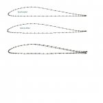
As I recall the new Sport Rotor blades were found to fly at a different disk tilt than others. I think they flew flatter. This caused the trim spring to need significant readjustment. I think it needed to be loosened. And on some gyros it required the offset distance to be changed. I think it needed to be reduced (from 1" to 5/8" for example).

Am I remembering this correctly?

And what causes the Sport Rotor blades to do this?

The reason I am asking is that I have my rotor head off and will soon install my new 27' Sport Rotor blades but I don't know which torque tube to use. I have two torque tubes for my Ken Brock heavy duty double bearing rotor head: one with a 1" offset and one with a 5/8" offset (original). I had to change it to 1" to use with my 25' McCutchen blades so I could use a normal trim spring at the back. With the 5/8" offset I needed a spring at the front to pull down.
 
Last edited:
I don't recall making any trim-spring or other changes when I installed the Sportcopters, Ken II. I did put on stiffer springs previously though.
 
The angle of attack of a rotor disc, Ken R, is solely determined by its lift/drag at any given airspeed. If the disc flies at an angle of attack of 10 degrees, its lift over drag is 5.67 (1/tan10º).

Trim spring tension is determined by cyclic flapping angle, completely unrelated to lift/drag ratio.

Flapping angle at any given airspeed is determined by the pitching moment coefficient of the blade airfoil.

Imagine an airfoil shaped like a venetian blind slat. Moving through the air, it has a tendency to twist nose down because of its curvature. The faster it moves through the air, the stronger the twisting. A negative pitching moment coefficient.

With such an airfoil mounted on your rotorhead, the advancing blade, having more airspeed than the retreating blade, twists more. This suppresses cyclic flapping; the blades don’t have to flap as much to equalize lift.

But the rotor disc must fly at an angle of attack determined by its lift/drag ratio; you tilt the rotorhead more noseup to accommodate it.

Suppressing cyclic flapping causes the rotor thrust line (the axis of the blade tips) to pass more rearwardly with respect to the rotorhead pitch pivot and thus requires more trim spring tension.

When Sportcopter took the same airfoil as used on your SkyWheels and flattened it out to improve the aesthetics (metal rotors with convex lower skins develop ugly oil can wrinkles from static droop), without a corresponding increase of trailing edge reflex, they unwittingly gave these blades a strong nosedown pitching moment coefficient.

On the other hand, as alluded by Ken J., you may not notice much need for an increase of trim spring tension. The spars are multicellular and look to be pretty stiff in torsion. Meaning they may not twist all that much.
 
Ken J.,

"Don't recall" - that's my problem. Are you getting old too?

Chuck,

Thanks for your help. The amount of pull needed by the trim spring is difficult to figure, so as to compare my McCutchen blades to my Sport Rotor blades. I guess I'll first try the 1" offset and if the trim spring pull required is too excessive I'll take it apart again and try the 5/8" offset. I guess that's the "fun" of the experimental aircraft hobby.

Steven,

I have talked to the "designer" several times, but can not get athoritative answers. His system of design, like most kit builders, is "trial and error testing" with "the proof being in the pudding". That makes it difficult to try his blades on different rotorheads and gyros that he does not have available to him for testing. For example, he could not tell me and would not recommend what teeter height to use for my gyro, but discribed how various teeter heights worked on his gyros and rotorheads. What I had to do was pick a height and then if it shakes have him make a different height, which he will be happy to do for me.

It appears that you have developed an "unusually vehement bias" toward Mr. Beaty. Sport Copter is a fine product. Owning one perhaps causes you to take comments on them personal. From an "outsider" perspective I don't read Chuck's comments as being biased or inaccurate.
 
Let’s not fight, Steve. Besides, I could use your help.

There is a simple method of calculating the susceptance of a transmission line stub that escapes me at the moment.

As an electrical engineer with a background in RF and microwaves, I imagine you have this stuff lined up for instant recall.

Incidentally, if you'd like to view the section data for Sportcopter blades, I can post it again.
 
Last edited:
Sportcopter superimposed on Skywheels ( NACA 8H12)
 

Attachments

  • Sportcopter.JPG
    Sportcopter.JPG
    24.3 KB · Views: 3
rehler said:
Chuck,

Please explain the polar plots. What is each axis represent?

Thanks.

Ist plot is Cd ( drag coefficient) vs Cl (lift coefficient). Chuck, by fixed wing standards, picking a point on the farther rt side of the curve, seems to give impressive L/D ratios. Are the SC airfoils significantly better than some of the other NASA shapes?

2nd plot is airfoil Cm (moment coefficient) vs angle of attack. As in previous post discusssion, the Cm is negative (wants to rotate fwd) and relatively flat across a large range of AOA. Chuck, are we still generating lift at the neg AOA values (wing section not symmetric)?

Cheers,

Mike
 
Ken R. , Keep in mind that I am just a dumb plumber! When I went to fly my SC's for the first time I was a little apprehensive about my trim spring tension due to things I have been told or read . I have an AC double bearing head with 4 1/4" from block to teeter bolt. I'll have to check the offset.

I set the spring tension for the minimum( head on back stop, enough tension to keep spring from just hanging there). It was great even up to 85mph.
I thought I was gonna have to double it up & all this stuff. But stick pressures were fine. But I had other things to think about, seeing how these were my first test flights. So I don't know where I will end up as far as spring tension goes, but it can't get much less with the spring & offset that I am using. My blades are 28' x8.5 .
 
Ken R. and all, I've gone back and changed the Sportcopter drag polar to show an 8H12 superimposed. (Oops! can't change a picture so I've deleted the original and will post below)

The 8H12 (Skywheels) shows a slight advantage over the Sportcopter as to lift/drag ratio but in the real and turbulent world of rotors, there would probably be no measurable difference.

The drag polar and moment plots were done with Javafoil, a desktop virtual windtunnel downloadable from Dr. Martin Heppperle's site:

http://www.mh-aerotools.de/airfoils/javafoil.htm

Javafoil plots closely parallel NACA windtunnel data for standard airfoils but it is not a real wind tunnel and real wind tunnels with nearly zero turbulence aren't the real world as seen by rotors.

Wind tunnel and Javafoil plots of the 8H12 show significantly lower drag than anyone has ever obtained in practice.

The pitching moment coeffecient is straight forward and simple. There will be no significant difference between calculation and measurement.

The admittedly crude measurements of rotor drag I've made using a straightedge (board) pivoted to a post with drawstrings to align parallel with the rotor tip plane as a gyro is flown past bear this out.

SkyWheels with NACA 8H12 airfoil had significantly higher drag than DragonWings

Rotordyne and Bensen blades had significantly higher drag than SkyWheels.

The NACA 8H12 is a "laminar" airfoil but maintaining laminar flow is tricky. The Javafoil drag polar shows sharp bends in the drag curve, indicating flow is ready to separate or at least transition to turbulent flow. I doubt if laminar flow has ever been achieved on a rotor with its constantly varying airspeed, angle of attack and diagonal flow.
 

Attachments

  • Sportcopter-8H12.JPG
    Sportcopter-8H12.JPG
    52.7 KB · Views: 0
Last edited:
Thanks for that Chuck.

IF I recall rightly you posited (a while back on Norm's conference) that a negative pitching moment could improve a rotor's stability - and it seems to me that it does indeed improve the gust response, although there could be a downside if taken too far.

Ultimately a severely negative pitching moment responds to increased load by pitching down, if it does that enough, the rotor RPM needs to rise even more than it would for a zero moment blade - and the teeter height would surely become invalid?

It is after all changing pitch, and that disrupts the relationship between load, RRPM, and coning angle, does it not?

One concern regarding the Sprtcopter analysis - the advancing blade flies faster than the retreating blade, sure, but both carry the same load, and the retreating blade load is effectively carried further out with increasing Mu.

So will the greater length from blade load to root being more torsionally soft cause the retreating blade to 'feather' in a similar manner to the advancing blade?

Obviously it all depends on the blade torsional stiffness, but am I straining at gnats?

All the best, Ben
 
I’m not so sure about negative pitching moment rotor blades, Ben. The rotary wing world has pretty much accepted zero pitching moment as the norm.

The suppression of cyclic flapping diminishes one source of 2/rev shake but creates another.

Cyclic feathering via elastic twist isn’t much different aerodynamically than cyclic feathering with a swash plate and feathering bearings.

The Cierva C-30 used a Gottingen 606 airfoil that had a fairly high nose down moment and had to be redlined for speeds above 130 mph; otherwise an unrecoverable dive could result.*

The first few dozen DWs used an unreflexed NACA 2311 airfoil with a neg. moment coefficient of ~0.05. They flew very well and perhaps had a bit less drag than the current reflexed version but stick pressure was high and the stick would reach the rear stop at ~100 mph.

*Incidentally, there is a pristine C-30 hanging from the ceiling of the Fantasy of Flight museum near here, bearing RAF radar calibration squadron markings. The early CH radar operated on a wavelength of 11 meters, precluding steerable antenna arrays; azimuth had to be determined by the phase of return signals arriving at 2 physically separated receiving antennas. The CH sites had to be individually and frequently calibrated; The C-30 fit the bill perfectly with each blade spar being a ½ wavelength reflector.

This particular machine is equipped with what looks like RAF-34 rotorblade airfoils. The reference material I have does not indicate use of the RAF-34 on C-30s.
 
Chuck, I've been under the impression that flapping angle also is a function of the slope of the airfoil's lift curve. A foil with a steep-sloped curve ought to require less cyclic pitch change to effect X% change in lift than one with a shallow-sloped curve -- therefore the steep-sloped one should have a lower flapping angle and require either more spring tension or less offset at a given airspeed.

Holding everything else constant, at least.
 
Doug, most any airfoil likely to be used on a rotary wing machine will have nearly the same lift slope.

The attached Javafoil plot shows an overlay or 3 different airfoils.

The blue line is an NACA-2311

The green line with round balls is an NACA-0009

The green line with crosses is an NACA-63012

The 2311 and 0009 are from the same family but the 63012 is a laminar airfoil with maximum thickness at 35% and a reverse curvature (cuspal?; tadpole?) afterbody.

The angle of zero lift varies with camber but the slope of the curve remains essentially constant.
 
Hi Chuck,

How does the lift curve Clalpha (Cla) of the the airfoil section itself differ from the overall disk Cla? Is their any difference?

IOW, we talk of a rotor disk flying at a trim AOA for dynamics discussions but we also speak of a blade section flying at a certain AOA+/- flapping. Are the
Cla s different or have any correlation?

Am I confused? :confused:

Thanks,

Mike
 
Mike, the lift slope of a typical airfoil is in the range of 0.1/degree depending upon aspect ratio.

The lift slope of a typical rotor is in the range of 0.02/degree.

This was discussed on another thread started by Gene Weber.
 
Top