Revolution Mini 500 Parts and MH-1 Upgrade

Brian,
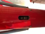
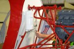
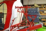
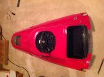
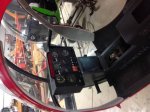
That's a Gopro apparatus. Mount the camera on it set the axle radius and pull it with a piece of long fishing line and get a ground view up circle of what you are filming.

Ah-Ha! Never would have guessed that!
camera-dolly-for-dslr-video-camera-smartphone_7b496031-78e7-4809-ba36-f8ac45cfbc61.jpg
 
I see the special "flex-coupling" for the T/R driveshaft in that same picture, right in front of the skate thingy. I have made some decisions on how I will configure my shaft so I will start another thread for the details and logic that brought me to my decisions. The helicopters that really confused me are the Robinsons.??? They have a long shaft that has no intermediate supports at all? The one bearing that is between the T/R gearbox and upper sheave is FREE to move radially in all extremes. It seems to me that it offers no support at all. I think it just acts as a damper to keep shaking from starting or worsening?
 
Last edited:
I see the special "flex-coupling" for the T/R driveshaft in that same picture, right in front of the skate thingy. I have made some decisions on how I will configure my shaft so I will start another thread for the details and logic that brought me to my decisions. The helicopters that really confused me are the Robinsons.??? They have a long shaft that has no intermediate supports at all? The one bearing that is between the T/R gearbox and upper sheave is FREE to move radially in all extremes. It seems to me that it offers no support at all. I think it just acts as a damper to keep shaking from starting or worsening?

Brian,
That's a NO Flex in that picture. Your way over thinking things again. Our moreflex works well and I feel very safe with it. You can spend more hours and time and material trying to reinvent the wheel, glad your spending your money doing it. I'm going flying you can reinvent the wheel again!!!
 
Last edited:


Brian,
That's a NO Flex in that picture. Your way over thinking things again. Our moreflex works well and I feel very safe with it. You can spend more hours and time and material trying to reinvent the wheel, glad your spending your money doing it. I'm going flying you can reinvent the wheel again!!!

You have one way of thinking, I have another. My way is to look to existing successful designs for understanding and following the lead of others. You say 1 Morflex works very well. That's only because it hasn't broke YET.

I have a junk extra driveshaft and the parts laying there on the floor. Zero $. One extra Morflex is all I will have to purchase (and bolts).
I intend to fly my helicopter to work many days, to Florida sometimes, and up in the mountains of Tenn and NC. Not just a few miles to my buddy's house.

The FACT is...your shaft is bowing in the 2' section from the front bearing support to the pinion input. Is that OK? Maybe so. Who knows? I do know that you can bend a piece of aluminum back-n-forth a few times and it will break. Your driveshaft is being bent back and forth. How long will it be before it fatigues? Who knows?

The ONLY thing that will be bending back and forth on my setup is black rubber donuts which are designed for that purpose and are rated to 6000 RPM with a 2 degree misalignment. My long shaft and short shaft will be 100% straight 100% of the time.

...By-the-way! The flipped front pinion bearing and 2-row angular contact rear bearing setup (which you claimed I was too stupid to see it couldn't be done) worked out perfect and was very easy to do without modifying the case or anything else. Just made a front spacer out of the unused outer cup race and shortened the inner spacer.

Brian,
Again you’re thinking outside the box! I have actually strapped a GoPro camera to the frame and watched the transmission movement and tail movement under all flying extremes. The main transmission moves less than .100 thousands of an inch. The tail rotor shaft doesn’t bow at all except very little at the moreflex coupler which it’s supposed to do. The original one wouldn’t flex at all that's why it broke!! My moreflex will never break on any of these machines. The only thing that could possibly fail on it is the rubber dampeners inside the moreflex itself; even then the bolts can’t come out at all. It may make a lot of noise but you will be able to make it safely down to the ground. We have done more testing with these machines than you will ever do! The transmission cannot move like you clam. The mast support is mounted ridged to the frame and even thou is has rubber mounted mast bearing it only moves less than it does at the moreflex. I have put a GoPro on every part that turns or moves and monitored them all in all flying conditions, Have you??? No you haven’t, so how would you know what you’re talking about! As far as my flying goes, I didn’t buy my helicopter to do cross country flights. I fly low and dangerous 90 percent of the time. I would never go anywhere to fly that I’m not familiar with. That’s how people hit power lines and other accidents happen. Also it was a promise to my wife not to fly cross country without be able to take someone with me and have storage for luggage or whatever when traveling. Now the new two seat helicopter will be a different story on cross-country. It will be a luxury machine with all kinds of baggage storage and will be one of the smoothest machines out there. If it’s not I’ll throw it in the trash until I get one that is. By the way I have never called you stupid nor will I ever, but you have done some incredibly stupid things in all of our eyes. I speak for all the people who call me going what the hell is he thinking. Ok now let’s talk about your backwards bearing arrangement. We all know how poorly designed the transmission already is. The only thing it had going for it was the direction of the pinion front bearing. Believe it or not that tapered roller bearing acts as somewhat of an oil pump; it pulls oil from the small end and pumps it back to the big end if it can get oil. That bearing its self, pumped oil to the pinion shaft. Now you have reversed the natural flow to the pinion. And with your scroll pump thing a ma jiggy spinning at that high of an RPM on the pinion shaft will blow every seal you have. Wait and watch! Just remember my helicopter and I have been nothing but a test machine and test dummy. Been testing and flying it since 2009, built many things like you talked about and threw them all away for certain reasons and started over till it was right. Now mine fly’s, and fly’s very well, and has been very good to me so far. One more thing if the transmission moved as you say, how in the hell would you ever keep that cogged belt in track??????????? The tail drive shaft at the most extremes of peddle turns and loading at most uses 17hp at the most, most of the time 5hp under normal flight and load. The shaft between the two carriers doesn’t flex at all, it only flexes at the moreflex. I’m not your enemy, I thought I was trying to help you from our experiences not just mine.
 
Francois,

You can have them..They are the upgraded pitch arms from Revolution.
I'll ask John what there worth and I'll give you a deal.

If I'm not down at the shop, John can send them to you....

Kevin

Hi Kevin,

I've just paid John for the pitch arms and back plates. Thanks for selling them to me, it was just what I needed.

Cheers,

F.
 
OK John. I'm pretty sure you are right about everything...:)
 
Great

Great

Hi Kevin,

I've just paid John for the pitch arms and back plates. Thanks for selling them to me, it was just what I needed.

Cheers,

F.

Enjoy,

Glad I could help...Fly safe

Kevin
 
Proven in the field

Proven in the field

OK John. I'm pretty sure you are right about everything...:)

Bryan,

John was and is the test pilot for the MH-1 upgrade. His design is proven and has been working without incident since his installation in 2009. I seen his design in person and I will say this: his moreflex coupler is a very good design. It allows the drive shaft to flex (very little) and has bolts that if in fact it did fail, it would not come apart. The stock Mini-500 drive system was not a good design. That's why when every owner pulled their tail boom off, there was rubber pieces laying all over the bottom. This was from the misalignment of the tail drive system as you are aware. If it failed, it hard failed.

Bryan, If your interested in another design, I will send you the info on my previous owners design. Here's a picture of the bearings he used. However, he installed one in the forward section where John's moreflex is and we noticed it did not flex enough so I decided to switch to John's design. However, my previous owner did fly his design with no issues.

I feel bad this thread is pointing fingers at everyone. It was and is intended to just show my progress in getting my old barn queen back in the air. John has many hours on his moreflex design and so far it's proven. I will have no issues in flying mine with his system. Just remember, the old system worked but make sure you keep taking the tail boom off and inspecting the rubber fingers. Because as you are aware, once they come apart in the coupling, there's nothing holding it together and down you will come.

Fly safe,

Kevin
 

Attachments

  • IMG_0056.jpg
    IMG_0056.jpg
    126.8 KB · Views: 10
Thanks Kevin,

The Morflex setup IS great. Right after John's drive flange ear broke-off. I suggested to him and Rick that the Morflex couplings on my Brantly had a 3200 hour life-limit and they were cheap and off-the-shelf.
He and Rick immediately took-off down that road. It was a great way to fix Dennis' original setup.

Now I will go off on my "opinion tangent." Dennis' setup on the original Alpha-Model Mini's (where the MRGB was hard-mounted to the frame) was a good, simple idea, and would have worked great too if the frame had not flexed, and IF (big if) builders made absolutely certain that the driveshaft was concentric with, and perfectly in alignment with the pinion shaft. Dennis' intention to use the big steel disk as a rotor brake in the future, was a better idea still. I have considered using it for that very purpose, in conjunction with the Morflex's. As we all know, even on the hard mounted Alphas, the flight loads allowed the long mast to flex the frame in all kind of directions.

Here's John's 12-1-2011 forced landing thread. http://www.rotaryforum.com/forum/showthread.php?t=32159&highlight=forced&page=2...post #22 is where I suggested to him on 12-4-2011 that the Morflex might be a better alternative. In post #19 he showed a picture of the drive flange ear that had broken off and said he was sending them out for failure analysis (great course of action). In post #23, Rick agrees that's the plan and thanks me for suggesting the Morflex as a solution.
 
Last edited:
Instrument Panel

Instrument Panel

Just got done building my new instrument panel. Joe Rinke made both pieces for me. I finished the pieces, cut, drilled, sanded, painted, measured and laid out my new carbon fiber panel. Here is some pictures of my new improved, bigger panel.
 

Attachments

  • IMG_0302.jpg
    IMG_0302.jpg
    132.5 KB · Views: 5
  • IMG_0306.jpg
    IMG_0306.jpg
    132.1 KB · Views: 6
  • IMG_0309.jpg
    IMG_0309.jpg
    132.2 KB · Views: 6
  • IMG_0316.jpg
    IMG_0316.jpg
    137.8 KB · Views: 6
Cowling Modification

Cowling Modification

I decided to cut my cowling so preflight and maintenance would be much easier. This is the tail piece that slides over the tail boom. I cut and installed a fiberglass lip. I will install fasteners to both pieces. Now, I can remove the whole upper cowling and slide the little piece back on the tail boom out of the way.
 

Attachments

  • IMG_0318.jpg
    IMG_0318.jpg
    134.3 KB · Views: 6
  • IMG_0151.jpg
    IMG_0151.jpg
    130.2 KB · Views: 6
I like that, Kevin...I may do something similar. Royalties?

smiles,
Charles
 
Up on skids

Up on skids

John and I got my bird up and back on it's feet. I had my friend Ron Prince re-do my seat and he added a nice red stripe. Ron made and embroidered my firewall interior as well. Nice job.
I will be mounting my new Yamaha Genesis 120HP 0 time engine that Rick built up for me very soon. Rick also finished rebuilding my tail rotor transmission.
John has my main rotor transmission upgraded and almost ready to install. John's been machining parts for me left and right. Control arms, backplates, clutch housing etc. I'm keeping him busy.
I just have to start putting her back together. I have all my parts bought and ready to install. I think we can get her done and flying sometime in the near future.
I will keep everyone posted of my progress.

Kevin
 

Attachments

  • IMG_0289.jpg
    IMG_0289.jpg
    131.4 KB · Views: 2
  • IMG_0293.jpg
    IMG_0293.jpg
    122.5 KB · Views: 2
  • IMG_0292.jpg
    IMG_0292.jpg
    123.8 KB · Views: 2
Enjoy,

Glad I could help...Fly safe

Kevin

Good Day John and Kevin,

The pitch arms and backing plates you sold me has just arrived. Thanks John for brokering the sale, and shipping me the items to down-under.

I have also received my first MH-1 spare part from John, to use on my Skeeter Jr. It's an increased size main drive gear, better suited to the Yamaha engine RPM range. Thanks for that as well John.

Cheers,

Francois

Francois,
Glad we could help you out. Sorry I haven't responded sooner, but Kevin has been here over the holidays and we have been working on his helicopter. By the way you still have some credit left.
 
Just a sneak a peek at this week ends progress. What a great Thanksgiving with friends and family.
 

Attachments

  • DSC_0002.jpg
    DSC_0002.jpg
    138.9 KB · Views: 3
  • DSC_0019.jpg
    DSC_0019.jpg
    133.9 KB · Views: 3
  • DSC_0017.jpg
    DSC_0017.jpg
    139 KB · Views: 3
Last edited:
Cowling modification

Cowling modification

My new improved airflow belly cowling was made by Joe Rinke. The airflow now will flow in the intake and be forced over the radiator. This will cool the radiator and make the engine run cooler. I put a 2350 CFM electric fan on the bottom of the cowling to pull cool air in while hovering or when the engine gets hot.
This system should work and let me keep my original cowling.
 

Attachments

  • IMG_0323.jpg
    IMG_0323.jpg
    132.9 KB · Views: 4
  • IMG_0324.jpg
    IMG_0324.jpg
    139.2 KB · Views: 4
  • IMG_0325.jpg
    IMG_0325.jpg
    144.9 KB · Views: 4
  • IMG_0327.jpg
    IMG_0327.jpg
    133.8 KB · Views: 4
New instrument panel installed

New instrument panel installed

John and I got my new carbon fiber instrument panel installed. It came out great and now looks like an instrument panel should.
The whole panel is very light and looks very nice.
 

Attachments

  • IMG_0339.jpg
    IMG_0339.jpg
    130.3 KB · Views: 2
Top