Jean Claude
Junior Member
- Joined
- Jan 2, 2009
- Messages
- 2,599
- Location
- Centre FRANCE
- Aircraft
- I piloted gliders C800, Bijave, C 310, airplanes Piper J3 , PA 28, Jodel D117, DR 220, Cessna 150, C
- Total Flight Time
- About 500 h (FW + ultra light)
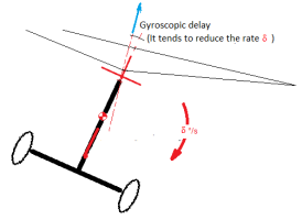
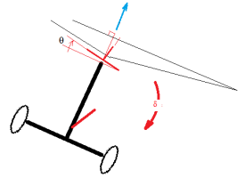
Everyone knows that the rotor of a gyrocopter is controlled by its hub: When this hub is tilted, it causes a cyclic variation of the pitch of the blades. The cyclic aerodynamic forces generated then force them to follow the desired plane, with the angular delay necessary to produce these forces.
I quickly calculated the delay θ at the orientation of the tip path plane, as a function of the pitch rate δ. The resulting formula is
θ ~ δ. (0.75 R m Ω) / 5 P (δ: rate of change of the rotation plane, R: rotor radius, m: mass of a blade, Ω: rotation rate in rad/s, P: rotor thrust).
For my light single-seat gyro project (i.e with m = 7.5 kg, R = 3.35 m, Ω= 42 rd/s, P= 2100 N the result is: θ° ~ 0.077 s . δ °/s
For example if the roll rate is 60 degrees per second, the rotation plane lags behind the hub by 0.077* 60 = 4.6 degrees. This delay shifts the thrust sideways by G and thus automatically decreases the initial roll rate (Caution: it is not stability, just damping)

Conversely, this also means that a continuous input of θ° from the hub to the structure (thanks to the stick) is required to maintain this δ°/s rate

But what about a control input starting with a zero roll or pitch rate?
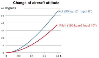
In this case, the balance of moments gives I.δ' = P.H. Sin (θ - 0.077. δ) with I the roll inertia, P the rotor thrust, H the distance of the seesaw above the center of gravity, and θ the abrupt control input angle.
This equation yields the curves below, one taking into account the roll an inertia of 90 kg.m2 and the other, a pitch inertia of 190 kg.m2

This tells us about the effectiveness of direct control
I quickly calculated the delay θ at the orientation of the tip path plane, as a function of the pitch rate δ. The resulting formula is
θ ~ δ. (0.75 R m Ω) / 5 P (δ: rate of change of the rotation plane, R: rotor radius, m: mass of a blade, Ω: rotation rate in rad/s, P: rotor thrust).
For my light single-seat gyro project (i.e with m = 7.5 kg, R = 3.35 m, Ω= 42 rd/s, P= 2100 N the result is: θ° ~ 0.077 s . δ °/s
For example if the roll rate is 60 degrees per second, the rotation plane lags behind the hub by 0.077* 60 = 4.6 degrees. This delay shifts the thrust sideways by G and thus automatically decreases the initial roll rate (Caution: it is not stability, just damping)

Conversely, this also means that a continuous input of θ° from the hub to the structure (thanks to the stick) is required to maintain this δ°/s rate

But what about a control input starting with a zero roll or pitch rate?
In this case, the balance of moments gives I.δ' = P.H. Sin (θ - 0.077. δ) with I the roll inertia, P the rotor thrust, H the distance of the seesaw above the center of gravity, and θ the abrupt control input angle.
This equation yields the curves below, one taking into account the roll an inertia of 90 kg.m2 and the other, a pitch inertia of 190 kg.m2

This tells us about the effectiveness of direct control


