Bill’s build ongoing saga.
Oh how wonderful it would to have a kit or at a minimum a set of plans where one could follow the toils of another on your personal path to the freedom of flight ( sans ads-b out) Actually that is not me at all. The challenge of this journey is, I find, quite stimulating if one can keep the depression at bay from the lack of MONEY!
This is the one problems with organically building something which has a lot of systems which have to work harmoniously together. Issues and challenges can compound themselves when you have taken on the work of others. Fox example, is it more cost effective and less labor intensive to build a new house or remodel one? Open for debate.
We stand upon the shoulders of giants and it would be foolish, in my opinion and manner of thinking, if building an almost scratch machine as not to include the design lessons given to us from the pioneers of our past. Also driving me is the overwhelming thought that this is my machine and I will configure it to my satisfaction.
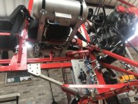
So with that in mind, I truncated the fuselage, fashioned the gussets and raised the CG to more or less in alignment with the thrust line of the power plant.
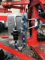
Smiling at my self, I then went to work hooking up the maze of of fuel lines connecting the tanks added because the 11 gallon seat tank would not allow me to wander far from the confines of the place which I left. What fun is that if you cannot explore the world via an open cockpit flying machine.
11 gallons many would say is quite enough and indeed it would be for some buzzing popular and expensive modern engines far from the monetary reach of this poor candidate of the air. So a semi run-out Lycoming with a guttural sound and a slow moving propeller is what will be pushing me through the air.
Yes very old school full of massive cubic inches and the requirement of adequate venting of the fuel tanks least they be sucked thin from the demands of such a beast. At best 7 gallons per hour and at worst 12 gallons per hour of a minimum of 92 octane free of the gasket stupefying alcohol our government has made so common.
The wood which it spins is 68x46. Calculations predict a maximum speed of 88 mph if the old girl can spin at 2700 rpm. Throttled back to an rpm which doesn’t require the application of carburetor heat of 2100 rpm,I have hopes of seeing my airspeed needle shake at 65-70 mph. This, which is a comfortable speed facing the brutality of the wind. We will see, for the many flat sided and what is worse, round structures protruding into the viscosity of the air makes even that modest goal doubtful.
I seem to remember, in ancient times when I trained on a Parsons and hearing the faint scoffs of those who knew or thought they knew, that the machine was a 55. It left the runway at 55, it cruised at 55 and it landed at 55. Kind of sad but I know what is coming. Parasitic drag can be improved and no doubt this will be a area for improvement once the FAA gives me the nod. 55 was indeed the final approach speed.
An engine of that pedigree requires that you be the engine control unit (ECU). The amount of monitoring Instruments and controls is daunting to oversee the health of that old engine.
I was thrilled that in my organic style of building and in my myopic world, I had stumbled upon a place to mount my fuel lines and electrical connections on an open frame machine and ( and this is a very very big and) to keep the source of spark away from the thing that burns. Granted, just how far can that be on a thing which is built from 1x2” aloooominum tubing. Well, it’s not far but each will have its little area enclosed to keep their mutual bad influences away from each other.
So happy I was till I returned my thoughts to the blessed rudder cables. Now they can saw through fuel lines and electrical bus’s. Mother of Pearl! What to do what to do? I can dip the little buggers below the arc of the propeller, skimming across the top of the rock guard and go under the non suspended and stiff Bensen style axle, flying under the gusset to climb ever so lofty to the altitude of the cockpit. Sounds great but do I really want those cables exposed as the lowest protrusion of the airframe? Drat!
Ok then, what about routing over the top of the gussets but then this gets in the mix of limited real estate in the area of the control yoke. Not good. What about marine push- pull cables? Talk about a love hate relationship on this forum. The options are varied and wide.
I expect something hybrid is or will be the answer. Push pull cables could be used with only the sheath being used to guide the cables though the danger zone so to speak and the rest be naked to the world for inspection otherwise.
In a not so normal nut-shell for me, I am looking for other methods than pulleys and fair leads to route the cables, which has to have a minimum of friction. There is that too.