I am Posting these for Rich so he can add details regarding the photos. He is quite excited about the progress and we are almost ready to start looking at engines...... Hope you enjoy these..... jtm
Also Please only reply at this thread (click on this link) so that we may keep the thread cleaner.
http://www.rotaryforum.com/forum/showthread.php?p=205828#post205828 Thank you very much !
Here's Rich.......
Thanks Jim. Its always a pleasure to have you help me present these photographs to our friends. With your professional help, it seems we always have something nice to show.
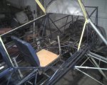
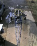
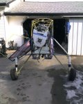
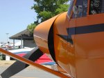
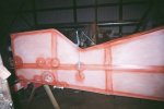
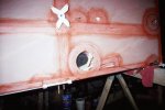
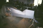
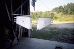
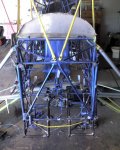
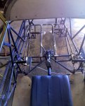
1. This picture shows the left side of the fuselege with the left rear window in place. As you can see, all of the left side, except the lower section, has been covered, doped and reinforce taped. If you look closely you can also see my radio antenna for the radio or VOR plainly on this side.
Look at previous shots to see the little bracket with its teflon plate which holds the coax firmly in place where it pierces the cloth fabric.
I didn't want any fluttering cloth near the opening which could possibly tear in flight. I also reinforced it with a circle cut out of the dacron and glued on and doped for that purpose. You will note the rivets were installed, and a coat of preservative zinc chromate had been applied over this, to prevent corrosion of the aluminum.
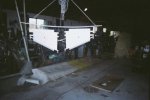
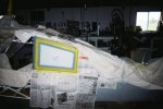
2. This picture shows the ELT antenna on the right side in good detail. If you look at the bar at the bottom of the window(the yahoo window), it now has a per cent enlargement window.
You can magnify any of these thumbnails in increments up to 400 percent. This will allow you to study the details of the work we did if you are interested, or care do do something similar to your littlewing.
You will also note the additional reinforcing circles and tapes over the glued joints in the cloth, at the fairleed window, and other horizontal stabilizer connecting tube openings.
These were just made by tracing the bottom of a coffee cup or tin can, on the dacron cloth, then trimming with a rotory pair of pinking shears.
The effect is very strong, and looks professional, to me at least.
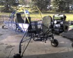
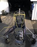
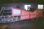
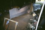
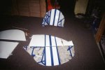
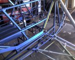
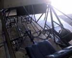
3. Here is a nice view of both of the top windows installed. They are still covered with the original plastic which is supplied on both sides of the plastic window material. It keeps the stuff from getting scratched and dirty during the building process.
As you see it it also has some blue paper tape attached around the edges to keep the epoxy paint off the plastic, until it dries. Nasty stuff to get off once dried!
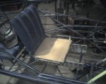
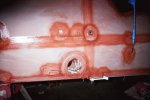
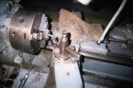
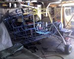
4. This view shows good detail of my fairleed windows. Inside the window is where the cable fairleed is attached to the airframe. I made mine with a teflon bushing which is split, so that it can be romoved without taking the cable out of the hole.
The romoval of the cable would be impossible, unless you cut the eyes off the ends, then made them all over again. On each side of the bushing is a hairpin like clip which can be removed to slide the bushing out either forward or aft from its location. Then it can be easily replaced with a new one if worn. If anyone wants a detail, I can supply it.
You will also note that the lexan window has some sheet metal screws around its perimiter. They are brass #10-32 machine screws which are tapped into an inner ring of the lexan for attachment. The inner ring was glued with gorilla glue to the cloth, then a reinforcing cloth ring was covered over it, then it was doped and sealed with the orange waterproofing stuff from Wicks Aircraft.
I then used the predrilled holes in the outer cover to drill through the inner ring (the holes were a tap drill size for the bolts to follow), in eight places, prior to attaching the outer window. By the way, all of the reinforcing plates, and these fairleed window details were made from scrap left over from making the windows on the project, so no added cost for the neat little details.
You can also see the plastic cable outlets from Wicks here installed. I also reinforce taped around them, prior to sealing and painting. These cost about four dollars per pair from Wicks.
The window could be left clear if one wanted too, but I chose to paint over mine to make it match the rest of the fuselege.
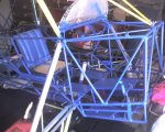
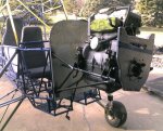
5. This view is just a detail of the same thing on the other side of the fuselege. On this side you can also see how my external trim bellcranks look after covered. They allow me to trim my elevators for fuel burn, or added passenger weight, without making all the trim adjustment to the rotorhead in flight. I hope that this keeps my controls in a somewhat normal condition throughout the flight taken.
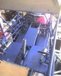
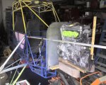
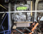
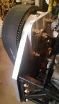
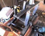
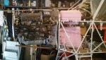
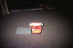
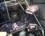
6. This is a shot of the battery on its 1/8" thick fiberglass base. I was able to get this from an electrical engineer friend of mine. The reason is that the fiberglass is strong, lightweight, and can be drilled and tapped for electrical connections. My solenoids for the engine, and prerotator will be mounted to it. I can also terminate my heavy duty leads to it, since it is a total insulator, without any problems.
You can see I made the mounting brackets from aluminum angle, and drilled out as many holes for lightening as possible. Also, I drilled 2" holes under the battery (6 of them) to remove additional weight from the fiberglass itself.
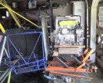
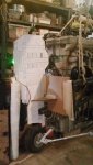
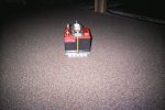
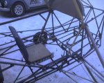
7. This shows the battery from the right side as it would appear in the fuselege. You can see my top mounting brackets and underside reinforcing where the thru bolts attach the battery to the fiberglass plate.
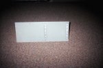
8. Here you can see the underside of the fiberglass battery plate, before I drilled it out under the battery to lighten it up some more. The battery is Wicks dry cell, with over 900 amps of cranking capacity. It should provide plenty of power to prerotate, then get the ignition running and starting the engine. It seems you can't have too much battery when you have an electric prerotator. My engineer friend and I have come up with a reduced amperage starting technique, to reduce the hit on the starter motor, and battery.
If any one is interested in our method, I can supply a sketch for your perusal. It allows a soft start, then full voltage, to get the rotor up to speed smoothly.
Thats it for this group. Best regards: Booster Rich


") well, at least every time we get in.....
well, at least every time we get in.....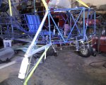
![Photo_010911_006[1].jpg](https://data2.www.rotaryforum.com/attachments/70/70767-eb9a05e45c1418e628856ef6ccd5bc56.jpg)