"Forget Bernoulli's Theorem"

Andino

Active Member
Joined
Mar 14, 2022
Messages
533
Location
Southhampton, U.K.
Aircraft
many FW airplanes + various autogyros
Total Flight Time
>1000 hours
I try to yearly reread flying's Old Testament: Stick and Rudder by Wolfgang Langewiesche (1944). To learn something new, read an old book. I'm only on page 10, and already found an old jewel:

The plane is inclined so that as it moves through the air, it will meet the air at an angle and thus shove it downward, in somewhat of the same way that the inclined plane of a snowplow, in moving forward against the snow, shoves the snow to the side.

The main fact of all heavier-than-air flying is this: the wing keeps the airplane up by pushing the air down.

In exerting a downward force upon the air, the wing receives an upward counterforce—by the same principle, known as Newton's law of action and reaction...which makes the nozzle of a fire hose press backward heavily.... Air is heavy; sea-level air weighs about 2 pounds per cubic yard; thus as your wings give a downward push to cubic yard after cubic yard of that heavy stuff, they get upward reactions that are equally hefty.

Bernoulli's Theorem postulates that wings "suck" from the top surface low-pressure effect, but Langewiesche disagrees. Wings (including rotating wings) push down. This is anecdotal to those of use who watched our spinning rotor push down the grass during the landing flare. We can even roll backwards from a stopped landing with aft stick if the rotor RPM is still high enough. Fun.
 
It is a combination of both, I would argue at lower Reynolds numbers, the bottom surface is planing more and the top surface is only providing the needed shape to smoothly transition the airflow over the structure and back to the trailing edge with a very small lift component.
At high numbers/speed, the top surface "sucking" has a lot more to do with the total lift force and the bottom surface can no longer be flat and needs the a curve to keep the laminar flow, but this curve is "Lifting" the wrong direction, so it is a trade off with angle of attack, position of max thickness for desired pitching moment and minimum effective dose of lower curvature to maintain attachment...Over simplified, I know...
On an anecdotal note, The indoor free flight modelers built little 22" span balsa hand toss planes that fly up to 2 minutes in dead air.
They use flat bottom foils that are a straight ramp to the trailing edge, with enough curve over the leading edge to prevent stalling and to provide the forward pitching moment that makes them level off after a hard climb. The top surface is only preventing separation in this low pressure realm.
 
We have a retired Air Force flight crew ??XXX??? that was on B-52's and C-141's.
We have discussed this on several occasions. He clearly states about "Impact Pressure" which impacts the lower surface of the wing during flight. He maintains there are addional charts for calculating liftoff points with heavy aircraft. and just like figuring for density altitude these "impact pressure" charts come into the equation.
 
Does a flow analysis with video, or Schlieren photography of air through the disk exit?
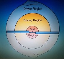
I am interested in the margins, or transition between the so called "driven zone" and "lifting zone"
and wondering if it is more of a smooth transition of drive vs. increased drag, and does the increased drag, lift area
tend to retard span wise flow, or increase it?
So many questions....
The handbook refers to air flowing UP through the disk, I think this is technically correct in that some air is starting at the underside and a percentage is leaving on the other side of the blade, but it is laminar and accelerating across the top surface, thus driving the blade (True sailing).
There is probably a large component of span wise flow that is creating drag and a wake, but I have not seen examples of this...
Any wind tunnel videos?
 
I don't follow your driven vs. lifting zone distinction. Do you mean driven and driving? Both make lift. There is no big change in flow at the boundary. It's just a question of orientation of the lift vector with respect to the axis of rotation.
 
The book says, and I have seen it elsewhere, that the center portion of the disk is providing the drive for the outer perimeter which is creating the lift.
Not sure that I entirely buy that, as the tips may still be driven at 300mph.,
But, it IS possible that the tips are creating too much drag to actually drive the rotor and an interior surface area greater than the tip area is doing the bulk of the rotational work. I don't know for sure, I can visualize a gradual reduction of driving force as you move out to the tips, but I can't completely believe any theory until I see proof of flow, or build physical models to prove it.....
I would think this ground has already been covered somewhere....
 
That's not quite what the book actually says.

If the force vector falls slightly behind the rotational axis, it will retard rpm (not the quantity of lift). If the vector aligns perfectly, it has no effect on rpm (nor on magnitude of lift). If it falls slightly ahead of the axis, it enhances rpm (still making lift). All those disc regions make lift. Only the stalled regions do not.

Driving / driven is about maintaining stable rpm, through balancing net rotational force, not about lift or flow behavior.

If the driving region did not make lift, it could not make driving force, and the spanwise lift distribution would be a structural disaster. Driving force comes from the tilt of the lift vector with respect to the rotational axis. It IS lift.
 
Last edited:
I didn't say the driving area did not create lift, but I am wondering how much the lifting sector is creating driving force.
The formula shown in the book does not include the sub vectors and they may not have distilled it as much as Marchaj.
 

Attachments

  • lft dgrm.jpg
    lft dgrm.jpg
    44 KB · Views: 3
They refer to the "Driven region" as the area creating lift, whereas the driving area is creating the driving force of the rotor.
Clearly, the farther inboard you go, the less lift, (or driving force for that matter) until you have nothing but turbulent air and stalled blades.
I would like to see the transition of flow from inboard to outboard blade span during forward flight, including the span wise flow and any
vortexes that are spilling out from span wise flow...


Sub vector was referring to the diagram from Marchaj and it details other lift vectors as well as forward components.
Probably should have left that out, or re=posted the diagram...
 
They refer to the "Driven region" as the area creating lift, whereas the driving area is creating the driving force of the rotor.
This is a false distinction. They both make lift. I am at a loss to state it more plainly.

The real difference is only urging or resisting increase in rpm.
 
Again, I am not saying the inboard area doesn't create lift. It definitely does until you move inboard to where it doesn't.....
They are saying the outboard area is not creating "Drive", it's being "Driven" from the inboard area.
And at some point inboard, there is no lift, or drive, this is the stalled area and it is probably accurate.
Is there enough inboard area to drive the outboard? Or is it all providing drive?
This is what I would like to quantify..
I would like to see this whole concept verified and charted, if it hasn't been already.
If it has, I am asking to be pointed to that information.
 
Last edited:
When the rrpm is steady, there is no acceleration or deceleration. So you can assume the sum of the torques driving and driven produced during a lap is zero:
Sans titre.png


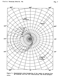
Attached is the stalled area of a gyroplane rotor during flight at different forward speeds (Naca report n°741)
Stalled up to 0.7 R on the retreating blade. This does not mean that this part does not carry anything
Sans titre1.png
 
Last edited:
Neither explanation is complete and adequate to explain everything that happens in flight.

This is like arguing whether light is a particle or a wave.
True, yet I never claimed that either was a complete explanation. Even Langewiesche admits: "...Bernoulli's Theorem doesn't help you the least bit in flying. While it is no doubt true, it usually merely serves to obscure to the pilot certain simpler, much more important, much more helpful facts."

A tidy video covers the matter in greater detail, provides partial solace to both camps, while adding the necessity of a critical third point: the Conservation of Energy (the downward deflection of air from both sides of the wing, which must push up the wing).

The handbook refers to air flowing UP through the disk,
A conversation about a gyroplane's rotor airflow is what gave me the impetus to post about it after reading Langewiesche recently. The downwash of a rotor is apparent on the ground surface from helicopters and gyroplanes, yet I've heard persistent allegations of an upward flow of air through the disc. Really?

A propeller is a rotating wing, of great camber which is only possible by the blade's short and stout construction. The "twist" of a prop is reduced in proportion to the blade's length of radius (which has greater rotational speed, and thus needing less Angle of Attack). We've all felt as bystanders the powerful thrust of a spinning prop, but who has heard of the powerful suction from the front side of the prop due to low-pressure of its cambered blades? There are airport warning signs for "prop blast" but none for "prop suction." To me, this is clear evidence of Langewiesche's assertion that Newton's Third Law (Conservaton of Momentum, with some help from the Coandă effect) seems more responsible for lift than Bernoulli's Theorem (Conservation of Mass). To be sure, Langewiesche's snow-plow analogy is simplistic in the extreme and not the total answer, but of the three Conservations the Newtonian Conservaton of Momentum seems the most cogent.
 
The downwash of a rotor is apparent on the ground surface from helicopters and gyroplanes, yet I've heard persistent allegations of an upward flow of air through the disc. Really?
"Upward" flow is correct if you interpret "up" properly. It does not mean upward with respect to the vector of gravity. It means air striking the underside of the disc/blades on a gyroplane (with the disc tilted backward in flight) and passing through the disc from there, as contrasted with striking the topside of the disc/blades on a helicopter and passing through the disc (with the disc tilted forward in flight). It is upward with respect to the disc on a gyro and downward with respect to the disc on a helicopter. The tilt makes all the difference. There is, of course, net downwash for any heavier than air flying machine, but which side of the disc is presented to the airflow is important for rotorcraft.

We've all felt as bystanders the powerful thrust of a spinning prop, but who has heard of the powerful suction from the front side of the prop due to low-pressure of its cambered blades? There are airport warning signs for "prop blast" but none for "prop suction." To me, this is clear evidence of Langewiesche's assertion.. .

To me, the absence of "prop suction" warning signs is clear evidence that few people are stupid enough to walk in front of a plane pointed at you with spinning blades, and the warning is unlikely to be necessary. Talk to any Navy veteran who worked on a carrier deck, and you'll find people who had to be concerned about "suction". And don't walk in front of the nacelle of a running jet engine unless you want to end up like one of those frozen chickens they toss in to test robustness against bird strike ingestion.

Suction warning sign:

warning-danger-sign-on-jet-600w-133332482.jpg

P.S. Bernoulli's principle is most commonly derived from conservation of energy, not mass.
 
Last edited:
That's a further addressing of upper vs. lower, but it still is not addressing whether or not the outboard area ("Driven") is actually solely being
"Driven", or is providing drive too. My gut feeling is that every part of the blade that is not stalled, I.E. the entire outboard 75%-ish of the blade
is providing drive and lift, but their assertion of the outboard section being driven is probably somewhat true because as you move outboard along the span, the drag is increasing and the apparent wind is moving to a lower angle of attack to the point that it is almost head on.
Eventually the tip can not go any faster because the drag overcomes the drive. This would be seen if you could telescope a blade outward.
Is there a finite tip speed for a rotor at a given air density and air foil? I would speculate, yes....
I have seen the NASA charts showing the propagation of the retreating stall area, but that is not addressing the actual flow dynamics of what is going on across the span. It's a generalization of the lift and stall zone.

A good study would be to take a timed out set of blades, install pressure sensors along the span, top and bottom every foot, and attach them
to a telescoping hub bar, then put the whole mess in a wind tunnel..

As to propellers, they are not a good comparison to autogyro blades because they are very positive AOA (can not auto rotate) and are being mechanically driven and have airfoils designed to maximize thrust.
A modern windmill is a slightly better analogy, however their airfoils are designed to maximize rotational thrust (extract max. energy from the wind) and minimize the lifting forces that are not contributing to forward movement. they are much lower AOA than lifting foils and
would push air the wrong direction if driven.

Autogyro blades are effectively trying to find the maximum point of rotational thrust and lifting force which at this
seems to be a compromise of the highest AOA possible while safely maintaining autorotation.

Again, I am questioning the complex detailed flow dynamics along the span of the rotor, not the generalities
and I have not seen anything more detailed than what has been presented in this thread...
Not looking for an argument, looking for answers...Maybe this should be it's own thread?
 
That's a further addressing of upper vs. lower, but it still is not addressing whether or not the outboard area ("Driven") is actually solely being
"Driven", or is providing drive too. My gut feeling is that every part of the blade that is not stalled, I.E. the entire outboard 75%-ish of the blade
is providing drive and lift
If that were true, stable rpm would not be possible. With everything providing "drive", the force would be unbalanced, and the rpm would simply continue to increase until something broke.
You need to make some sketches at various span stations of the relative wind, axis of rotation, and net aerodynamic force vector to convince yourself.
 
The difference between "drive" and "lift" is just that the lift vector on the driving region is both upward and forward, whilst that of the driven region is upward and perhaps slightly aft. Look again at the vectors Jean Claude has kindly provided.
The forward component must at least match any backward component, plus all drag, else the rotor will start slowing down.
When there is excess forward component, the rotor will speed up, of course.
 
Last edited:
If that were true, stable rpm would not be possible. With everything providing "drive", the force would be unbalanced, and the rpm would simply continue to increase until something broke.
You need to make some sketches at various span stations of the relative wind, axis of rotation, and net aerodynamic force vector to convince yourself.
Apparently you missed the sentence after the sentence you quoted?

" but their assertion of the outboard section being driven is probably somewhat true because as you move outboard along the span, the drag is increasing and the apparent wind is moving to a lower angle of attack to the point that it is almost head on.
Eventually the tip can not go any faster because the drag overcomes the drive. "

You are trying to argue a point am in agreement with. The question is:
Exactly where is this drag build up happening?
All the info I have seen so far is very general and is not taking other variables into account.
 
Top