Focke Achgelis Fa 330

Does your calculation indicate any stalled regions?
How do you detect them and how are they treated in the calculation?
Does your calculation use two dimensional profile data?
Which induced velocity distribution do you use around the rotor disk?
How is the torsional deformation taken into account?
 
Last edited:
Does your calculation indicate any stalled regions?
How do you detect them and how are they treated in the calculation?
Does your calculation use two dimensional profile data?
Which induced velocity distribution do you use around the rotor disk?
How is the torsional deformation taken into account?

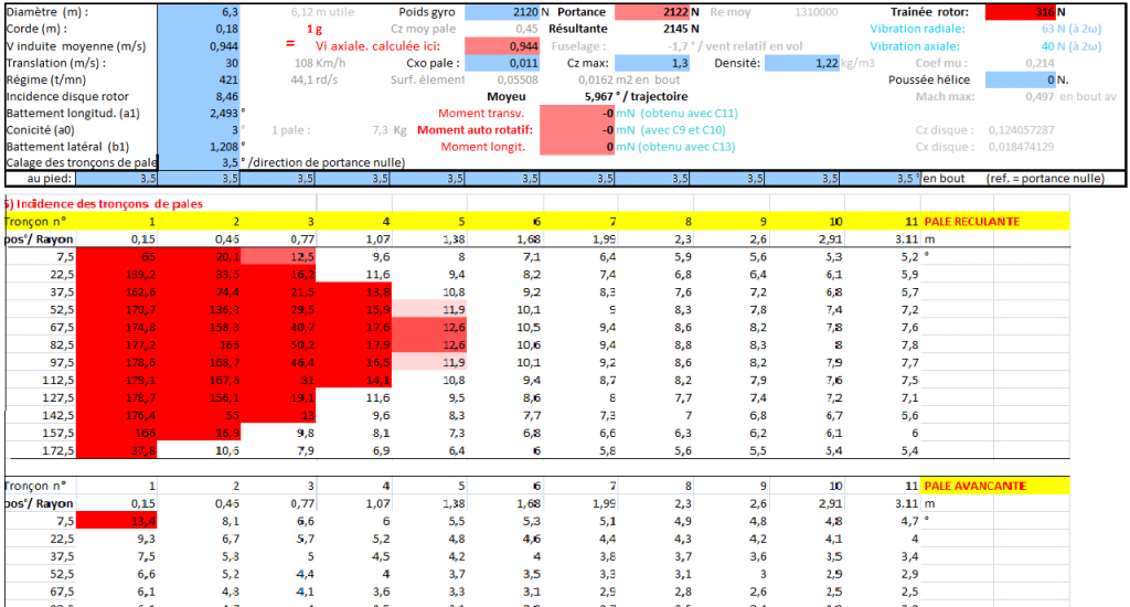
In EXCEL, spreadsheet of eleven columns, eleven blade elements were analyzed every 15 ° of rotation (24 lines). For each of these sections and in each of these positions were calculated:
- Their air speeds taken from the direction of the chord (Table 1),
- The coefficient of local induced velocity normal to the disk (Table 2)
- The axial component of the flow velocity through the disk (Table 3)
- Their Angle of attack (Table 4)
- Their CL, linked to the A.o.A , taking into account the stall. The section 11 is assumed halved because loss in tip(Table 5)
- The induced local flow (Table 6)
- Their lift, linked to the CL. (Table 7)
- Their CD, taking into account their CL, including post-stall (Table 8)
- Their drag (Table 9)
- The angle of the resultant relatively to tip plane (Table 10)
- The magnitude of resultant (Table 11)
- Their rotation torque in tip plane (Table 12) and their sum.
- Their flapping torque (Table 13) and their sum.
- Their axial component (Table 14) and their sum.
- The radial component (Table 15) was added to observe the vibrational component of the drag.
Each table uses the input data and those obtained in the preceding tables. The input data is in the blue boxes and are corrected gradually until the desired total lift at the same time that the cancellation of torque. Similarly, longitudinal flapping angles (a1) and transverse (b1) are adjusted to obtain a null transverse and longitudinal moment.

Does my calculation indicate any stalled regions?
Yes, comparing table #5 value with limit corresponding to input "CL max"

How are they treated in the calculation?
Post stall, CL is assumed 2,2. SIN (i). COS (i)
and CD is assumed 2 SIN^2 (i)

Does my calculation use two dimensional profile data?
No. Just input CD min. added to induced CD taking into account the aspect ratio of the blade.

Which induced velocity distribution I use around the rotor disk?
Average Vi is multiplyed by the coefficient: 1 + (r/R COS(alfa). COS(psi))

How is the torsional deformation taken into account?
Torsional law is eventualy added to corrected the local pitch setting (input data in the head of the eleven columns). Cyclic deformations are not treated.

Example (Input in blue case):
 
Last edited:
Dear Jean Claude,

first I feel I have to apologize for simply firing half a dozen questions at you, without any polite introduction or ending. My only excuse is that I wrote this post yesterday around midnight just before I went to bed and I wanted to get it out the door before I dropped.
Your analysis seems to be very thorough and considerate. Your treatment of the stalled regions seems to be quite a good engineering approximation that should capture the major effects really well.
The only assumption where a somewhat larger error might be introduced is that of torsional stiffness especially for the 90mm chord blade. The well known video of a rotating blade (https://www.youtube.com/watch?v=Ug6W7_tafnc) shows that even a fairly wide and well designed blade whips around pretty wildly. A 90mm chord blade will probably more behave like a wet noodle than a stiff body, at least that's what my engineering tummy tells me. To capture this effect one would have to use - and probably extend - Bruno Zilli's analyis. http://www.rotaryforum.com/forum/showthread.php?t=38611

Let me offer one small suggestion on how to improve the calculation at the end: reprogramming Martin Hollman's blade analysis I found that he introduced a fairly substantial error by using an equidistant spacing for the integration stations. The naca report upon which his program was based used stations that would cover the same disk area when swept around through 360 degrees. With this spacing accuracy was doubled with the same number of stations. It would be fairly simple to introduce such a spacing in your excel sheet. Just my two cents.

Thank you for your long and thorough explanation!
 
The only assumption where a somewhat larger error might be introduced is that of torsional stiffness especially for the 90mm chord blade.
Of course, Juergen. That is why I not have build lower 180 mm
 
Hi Chuck,

Yes, the two blade UH-1s and AH-1 had a definite "bump" especially when pulling a 60 degree bank and the blades cone more so than normal.

Wayne
 
The diagram below is from this site:
http://dy.163.com/wemedia/article/de...405179FQK.html

When I threw the caption at Google Translate I got this:

This is a chart of numerical simulation and large wind tunnel tests conducted by the US aerospace academics on the Fa 330 rotorcraft


which seems to make sense. This raises a few questions:
  • Which report does the diagram come from?
  • How are the boundaries calculated, which are indicated on the diagram?
  • Why is the diagram to be found only on Chinese sites? -
  • How did the Chinese obtain a report that nobody in the Engslish speaking world seems to have?


It's actually a bit frustrating that the Chinese now seem to be ahead in research of an aircraft that was entirely conceived flown and tested in the Western world FA330kiteA.gif
 
The 7th lecture at the Helicopter Association of Great Britain by O. L. L. Fitzwilliams, held on the 25th of October 1947, is a description of flight tests carried out after an FA-330 had been captured during the war and, lo and behold, this lecture actually is the one the diagram in my previous post comes from...heureka......;-)


The text starts at p. 174 of the pdf document, which is available here:
https://archive.org/details/journal00britgoog

You might have to register to be able to download the file.
 
Last edited:
You are a mine of documentation, Juergen
Thanks again
 
No Title

That PDF you've found, Jürgen, is very valuable... Among other things, there's a lecture by Raoul Hafner, in 1946, on the development of rotating-wing aircraft. I find specially interesting his definition of the auto-rotative state as a particular case, a point in the line between a powered and a windmilling rotor...


​​​​​​​
 

Attachments

  • photo127866.jpg
    photo127866.jpg
    55.4 KB · Views: 3
  • photo127867.jpg
    photo127867.jpg
    10 KB · Views: 3
Dear Javier and Jean-Claude,

thank you for the kind words, to which I would like to reply with another little piece of information. On page 11 of the report the parts of the 330's control system are depicted. The length of he lever arm for lateral tilt is quite a surprise to me. I wonder how it was actuated, the two control cables that operate it vanish in the lower part of the rotor column but it is not clear how they actually moved the lever arm


Jeff, you are right, this is a pull rope pre-rotator. Something similar has been used on early Cierva Autogyros.

http://www.cdvandt.org/FIAT-176.pdf
 
Juergen,
I still have not clearly understand the kinematic for the roll control of the Fa 330.
Except two cables coming from the stick and rising by pulleys inside the mast upwards.
At the top, I do not see how they tilt the pivot.
If you find the answer, please let me know.

For the first time, I see here the roll pivot was offset laterally relatively to the head bearing to compensate for the force on the stick due to angle b1
Thank you Juergen for this document.
 
I still have not clearly understood the kinematic for the roll control of the Fa 330
Unfortunately this is exactly the point which I have also not figured out yet, Jean-Claude, but there is hope!!!! I had started this thread in 2009 when I read the story of Sigurd Sauer who had finished a replica of the Fa-330 back then, so today I decided to phone him. We had not much time to talk because he was very busy with ...guess what... well, he is preparing the replica for flight tests!!!!! From our brief conversation I understood that he has been working together with a company for some time now to make his replica airworthy. The tests are currently scheduled to start some time in August, so after some seventy odd years an Fa-330 will take to the skies again!
I will send Sigurd copies of the documents that have come up recently. Sigurd has been very helpful in the past, sending me e.g. drawings with the exact blade profile of the Fa-330. I will ask him to send me a little sketch of exactly how the two control cables actuate the lever arm of the rotor roll axis and of course I will keep in contact with him to find out about the flight tests.

So much for today, stay tuned for updates...;-)


Malheureusement, c'est exactement ce que je n'ai pas encore compris mois non plus, Jean-Claude, mais il y a de l'espoir !!!! J'avais commencé ce fil en 2009 lorsque j'ai lu l'histoire de Sigurd Sauer qui avait terminé une réplique du Fa-330 à l'époque, alors j'ai décidé aujourd'hui de le téléphoner. Nous n'avons pas eu beaucoup de temps pour parler parce qu'il était très occupé avec ... devinez quoi ... eh bien, il prépare la réplique pour des vol d'essais!!!!! À partir de notre brève conversation, j'ai l'impression qu'il a travaillé avec une entreprise depuis un certain temps maintenant pour mettre son réplique en état de vol. Les tests sont actuellement prevues de commencer au course du mois d'août, donc après quelques soixante-dix années, un Fa-330 reprendra le ciel!
J'enverrai des copies des documents que j'ai présentés récemment ici a Sigurd. Il a été très gentil dans le passé, m'envoyant par exemple des dessins avec le profil exact du pale du Fa-330. Je vais lui demander de m'envoyer une petite esquiss de la manière exacte comment les deux câbles de commande actionnent le bras de levier de l'axe du rouleau du roteur et bien sûr je vais rester en contact avec lui pour suivre les essais de vol.

Aujourd'hui c'est tous, restez à l'écoute ... ;-)
 
Last edited:
There is an intriguing detail here. Approximately in the area of the end of the roll lever arm.
 

Attachments

  • Sans titre2.png
    Sans titre2.png
    163.8 KB · Views: 16
I tried to ask Sigurd about it today and I think you are pointing at the right spot, Jean-Claude, but didn't really get what he said. I will try to find out more.....
 
This afternoon I phoned Sigurd Sauer once again and he was so kind as to explain the lateral control of the Fa-330 to me. On many pictures one can see the quadrant that is attached to the lateral axis of the stick. The two parts of a cable running around the quadrant pass via deflection pulleys at the lower end of the rotor mast and vanish inside the mast. The attached sketch shows, that these two cables end at a 40 mm wide cross piece that is attached to the lower end of a lever which actuates the lateral axis of the rotor head. The two cables cross each other inside the rotor mast to give the maximum lateral force at the attachment points. The lever arm is part #2 in the exploded view on page 11 of the F.I.A.T. report 176 in my post #51 and I think that #15 is the cross piece.
In the WWII Wag Tails the cables ran directly to both ends of the cross piece #15. Sigurd Sauer has added deflection pulleys inside the rotor mast to still increase the lateral force. He told me that the lateral head movement is 6.5° degrees to one side and 10° degrees to the other. The rotor mast has a diameter of 80mm. To give the maximum possibel length of the lever arm the lateal axis must be offset due to the assymmetric lateral travel of the lever arm. Setting up three equations in three unknowns one finds that the offset is about 4.25 mm and the maximum possible lever arm is then 139 mm. I did not ask Sigurd whether the offset really exists, so this is just a guess but basicly the question as to how the lateral head tilt of the Fa-330 works is now solved.

The sketch below depicts the lateral lever arm and cross piece in the two extreme positions.


PS: some rough measurements seem to indicate that the lever arm is longer than the 139mm calculated above. One possible explanation is that the crosspiece could be aligned with the lateral axis. This would actually ensure that the two control cables can not chafe one on the other at the point where they cross inside the mast. Fa-330_lateral_rotor_control.jpg
 
Last edited:
Thank you Juergen for clarifying the mystery. The FIAT's sketch now becomes comprehensible.
The advantage of this arrangement seems to be that the mast serves as a roll stop for the rotor head.
 
Juergen,
Why do you think that the lever 2 is asymmetrical relative to the mast?

In my opinion, lateral flapping angle b1 only requires the asymmetry showned in this sketch.
So, the residual moment on the stick disappears and the RTV is centered. Sans titre1.png
Sorry, the tilt is in opposite direction. Corrected in post # 65
 
Last edited:
Top