Coaxials and their workings

alexkmmll

Newbie
Joined
Mar 14, 2013
Messages
5
Location
Monona, WI
Hello everyone,
As I'm sure you've noticed, this is my first post here. I thought I'd introduce myself. My name is Alex and I very much enjoy flight, however, I do not possess a pilot's license (Someday soon, maybe). With that said, I enjoy spending many days at EAA's annual AirVenture, and I also fly and work with RC aircraft.

Recently, I was reading an article in Popular Science. The article, about an engine, the NorEaster, said that the engine, which used cams instead of crank shaft, had low enough RPMs to be directly linked to a light coaxial helicopter. Well, I found the full report written, and found it less than conclusive on the subject, yet got my mind turning.

I would like to design a simple, legal Part 103, coaxial helicopter. Not necessarily build it, but design it; for fun, really.
Problem: I know very little about real coaxials. The RC ones are easy: Fixed pitch, swashplate on bottom blades, and two motors with varied speeds for yaw. However, this, obviously, does not transfer over to the prototypes. I scanned through a few images and found some with fixed pitch, some with collectives, a mix of all sorts of different rotor head configurations, and they all left me relatively confused. :der:

The other thing beyond me is yaw. It's from varying rotor speed, but how do you do this when you are powering everything from a single engine? I did a bit of research and found tip brakes and the use of differentials. So, if I understand this correctly, the brakes are deployed, causing the blades to decrease RPM, which is allowed through the diff, and the helicopter yaws? What other solutions are there to get around this? And how exactly are tip brakes connected to the actual rotor head when it's a cable? I read somewhere it's recommended the tip brakes are independent from other functions.

What gearboxes do these helicopters use? Have direct drive systems ever been attempted?

I am very sorry for all these seemingly dumb questions. Is there a 'beginner's guide to coaxials' anywhere? Ha!
Maybe someone can lay this out in a slightly more organized, understandable fashion for me? I'm very used to designing planes, not helicopters! Planes seem much more straight forward to me...

Thanks and sorry again,
Alex
 
I'm not sure that direct drive train has ever been attempted. RPMs too high will destroy the rotor system. The Airscooter is coaxial, but fixed pitch. Yaw is controlled by the paddles aft. It's a control surfave that utilizes the slip stream/rotor down wash to yaw(turn) left & right. Fixed pitch has not auto rotation ability.

https://www.youtube.com/watch?v=LlO0RTCXUpE

The Nolan Coaxial. Looks as if the dif gears are between the hubs.
Same thing with the yaw paddles.
https://www.youtube.com/watch?v=0QHfBucsL0Q
 
The GEN H4, like the airscooter is fixed pitch with gimbaled mast platform. Again no Auto rotation. The Airscooter uses a CV joint with gimbaled masts and the GEN H4 just gimbals the power plants, gear reduction and masts.

https://www.youtube.com/watch?v=sDC8Cs5gmqc
 
How about a collective coaxial that uses differential pitch? Has this been tried? I found an animation online that uses it, and it makes sense to me, really. Constant rotor speed, with a swash for each rotor, and a pitch differential assembly for the top rotor only. In my opinion, this would greatly simplify the overall design by removing all differentials and utilizing the pitch, instead. From looking at the animation, though, I would assume the pitch differential runs through the entire rotor shaft?

Coaxial Helicopter Rotor Animation - YouTube

Alex
 
Without collective pitch I wouldn't even consider flying more than about 3' high or faster than walking speed. Ask yourself what happens if/when you lose power.

Tip brakes for yaw don't work by slowing one rotor down, they add drag independently to one or the other - if power isn't balanced between them you'll yaw.
 
Juergen,

Thank you for the reply. I did take a look at your posted papers. It's unfortunate that they're mainly geared towards small models and data collecting, because I'm having some trouble understanding a few mechanical things.
The biggest one is the collective. In models, this is all controlled by servos, and the linkages are direct and relatively easy to understand. In order to move the collective up, all the servos move, while cyclic pitch can be maintained by moving each servo individually. However, in a small helicopter with all mechanical links, how does the collective move without interrupting with the rest of the controls?

Alex
 
In the first 20 seconds of this clip you see how the whole swash plate moves up by moving all the push rods in the same direction. This is how collective is applied, all blades change their angle of attack by the same amount. If e.g. one rod moves up and the other one down as is shown a bit later the the blades increase pitch when they pass the portion of the swash plate that's higher and decrease it 180 degrees later. This is how cyclic input is generated.
S-61 Sea King Rotor Head Animation - YouTube

this is also explained here:
How to: fly a helicopter - YouTube
 
Last edited:
I should have made this more clear, so my bad on this one. My confusion isn't with the collective and swashplate itself, because I do have a fairly complete understanding of these. My actual problem is the connecting rods to them. Basically, how are they connected from the input, or the controls, to the output? How do the rods move together?

Alex
 
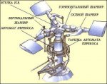
The picture below on the left hand side from here:

http://avia-simply.ru/avtomat-perekosa-vertoleta/

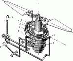
gives a fairly good idea. Assuming that the horizontal push rods are fairly long then, what little interference between collective and cyclic is in the gearing, is easily compensated by an ever so slight movement of cyclic when collective is used. Connection to the controls is via bell cranks as shown in the second picture from here:
http://y-savinskiy.ru/gl-26-35/uriev/

A slightly different system as used on the S-51 is here:
http://fly-history.ru/books/item/f00/s00/z0000014/st056.shtml

Then there are several drawings in this one:
http://www.rotaryforum.com/forum/showthread.php?p=508014#post508014


Last but not least here's how the two swash plates are stacked one above the other for a coaxial rotor:
http://fly-history.ru/books/item/f00/s00/z0000014/st050.shtml
 

Attachments

  • AvtomatPerecossa.jpg
    AvtomatPerecossa.jpg
    22.5 KB · Views: 1
  • AvtomatPerecossa_cr.gif
    AvtomatPerecossa_cr.gif
    13 KB · Views: 1
Last edited:
PRA Chapter 18 has a Nolan for sale. Talk to Adam [pres.] or Tom [v.p.].
 
I am still a bit confused on how the collective is actually mixed with the cyclic before going to the swashplate. I found this diagram, is this the 'common' arrangement used in small helicopters, or is it at least close?
Picture1.png

It seems to make sense and doesn't appear to put much tension on the cyclic control rods going to the stick, but it seems a bit crude. What are some of the ultralight helicopters using?

Also, carbon fiber frames/components. Does anyone know if carbon fiber is becoming popular at all for frames or flat components? It would save quite a bit of weight, but it will shatter under enough force. It doesn't just bend like aluminum does. Would it be safe to use as a frame, or would a 'traditional' aluminum frame be safer in the event of a crash? Could landing gear made to absorb all the shock from impact allow the use of a carbon fiber frame?

Alex
 
Alex,

The collective lever inputs move together. Notice that when these inputs move down, it moves the fulcrom point for the cyclic controls. This action moves the entire swashplate up and thus increasing the angle of attack of all rotors equally around 360 degrees of the of the rotor disk. However, the cyclic inputs move independantly, thus only adding angle of attack to a certain point on the rotor disk. As the rotor moves through this point on the disk the angle of attack is increased and then decreased as that blade leaves that point on the disk. This provides additional lift in that direction and creates the movement. Hope that helps. I dont know about small aircraft but that diagram is close to what it looks like a Huey.
 
This was a small coaxial proposed by Kamov;

This is information on the Coaxial configuration;
And this is some 'control' information that is specific to coaxials;
"During autorotation, the airflow through much of the disks is reversed. A particular pedal input would now cause a yaw in the opposite direction, if it were not for 'pedal switching linkages' that automatically take place in Kamov's at the onset of autorotation. "

______________________________​

Alternatively, for a better configuration; :)

FL 282 Control Diagram ~ Code for Control Diagram [After the two pages come up, click on them to enlarge.]


Dave
 
Top