- Joined
- Oct 30, 2003
- Messages
- 18,374
- Location
- Santa Maria, California
- Aircraft
- Givens Predator
- Total Flight Time
- 2600+ in rotorcraft
Colnfused on a higher level
Colnfused on a higher level
Thank you Gabor,
I am delighted you enjoy the thread; I wish you were here to make fun of her as she comes together.
I like the way India looks better too. Now in my opinion all three of her legs are similar rather than looking like her back legs were broken.
It appears to me that the India main gear is lighter, simpler and stronger.
The interface between the axel/caliper is more difficult to fabricate and will use an aluminum axel.
The links will be sheet steel and tapered in two directions. We want a radius on the corners so we will send it out to a fellow in Grass Valley, just up the road from Greenwood.
The pivot bearings will be high molecular weight plastic and split to aid assembly.
We have two different schemes to control the roll resistance and at this time it uses two smallish, long coil over dampers.
The legs will be made from the same Aluminum strut material that the front suspension is made from and have a straight link out of smaller aluminum streamline near the bottom between the adapter plates. India should be about 2/3 the weight of Charlie.
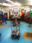
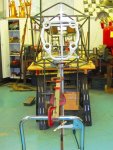
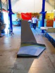
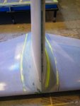
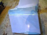
The old keel we are scrapping is about six weeks of work.
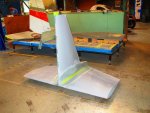
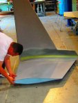
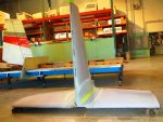
I like the looks of the new keel with its graceful bend and more gentle angles. I feel the air will like it better too.
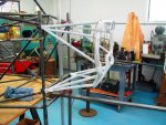
I did my weight calculations for the keel again this morning and the main tubes (7/8 .049 wall) for the keel should weigh less than 6 pounds.
We are using 7/8 .049 wall 4130 for the four main keel tubes because that is what Jim has the most bending dies for.
The lower tubes have a larger radius than the upper tubes.
The lacing is half inch .049 wall except the pieces that are directly across and they will be smallish .049 streamline tubing so it might account for another two pounds.
The reinforcement at the bend will be .040 sheet. It should weigh less than a pound.
It appears that the weight of the assembly is less than half the weight of the old keel and attaching bridge.
We are intentionally making it more flexible in bending and stiffer in torsion.
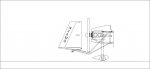
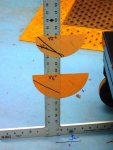
The picture is of the old keel without the attaching bridge that we are scrapping.
Hello Jeff,
I am glad you asked because I find value in trying to explain it.
I believe you are correct.
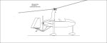
My cad program is still crippled.
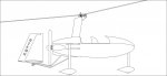
I made a very rough doodle of the new keel and then made it worse by converting it to jpeg.
The upper tube of the keel on each side will attach to the frame just below the upper engine mount.
The lower tube will attach to the back of the lowest part of the frame.
They are converging horizontally throughout their length.
They will still have considerable horizontal separation as they pass under the propeller and some vertical separation to get some beam strength.
We feel the vertical week point of the truss is under the propeller because the tubes are close to parallel vertically after they pass the propeller so we will have a gusset plate with fish mouths to spread the load.
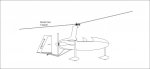
The new scheme for mounting the empennage is to come out through the bottom of the horizontal stabilizer with some plates that go directly to the spars rather than notching the spars and having a right angle box like we have now.
Because the tubes are splayed wider horizontally the loading is less localized.
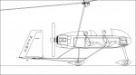
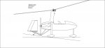
The drawing is made from one of the earliest versions of the suspension in the flight position so the arms are not yet tapered and the pickup points are not yet located. There will probably be a coil over dampener on each side outside the frame but inside the body. The will be driven by an arm like the ones to the struts but at a different angle off of the lower link. All the attachment and stress points sort of fell into place as we handled the metal.
You can see why Jim was confused when I tried to describe it.
Thank you, Vance
Colnfused on a higher level
Thank you Gabor,
I am delighted you enjoy the thread; I wish you were here to make fun of her as she comes together.
I like the way India looks better too. Now in my opinion all three of her legs are similar rather than looking like her back legs were broken.
It appears to me that the India main gear is lighter, simpler and stronger.
The interface between the axel/caliper is more difficult to fabricate and will use an aluminum axel.
The links will be sheet steel and tapered in two directions. We want a radius on the corners so we will send it out to a fellow in Grass Valley, just up the road from Greenwood.
The pivot bearings will be high molecular weight plastic and split to aid assembly.
We have two different schemes to control the roll resistance and at this time it uses two smallish, long coil over dampers.
The legs will be made from the same Aluminum strut material that the front suspension is made from and have a straight link out of smaller aluminum streamline near the bottom between the adapter plates. India should be about 2/3 the weight of Charlie.
The old keel we are scrapping is about six weeks of work.
I like the looks of the new keel with its graceful bend and more gentle angles. I feel the air will like it better too.
I did my weight calculations for the keel again this morning and the main tubes (7/8 .049 wall) for the keel should weigh less than 6 pounds.
We are using 7/8 .049 wall 4130 for the four main keel tubes because that is what Jim has the most bending dies for.
The lower tubes have a larger radius than the upper tubes.
The lacing is half inch .049 wall except the pieces that are directly across and they will be smallish .049 streamline tubing so it might account for another two pounds.
The reinforcement at the bend will be .040 sheet. It should weigh less than a pound.
It appears that the weight of the assembly is less than half the weight of the old keel and attaching bridge.
We are intentionally making it more flexible in bending and stiffer in torsion.
The picture is of the old keel without the attaching bridge that we are scrapping.
Hello Jeff,
I am glad you asked because I find value in trying to explain it.
I believe you are correct.
My cad program is still crippled.
I made a very rough doodle of the new keel and then made it worse by converting it to jpeg.
The upper tube of the keel on each side will attach to the frame just below the upper engine mount.
The lower tube will attach to the back of the lowest part of the frame.
They are converging horizontally throughout their length.
They will still have considerable horizontal separation as they pass under the propeller and some vertical separation to get some beam strength.
We feel the vertical week point of the truss is under the propeller because the tubes are close to parallel vertically after they pass the propeller so we will have a gusset plate with fish mouths to spread the load.
The new scheme for mounting the empennage is to come out through the bottom of the horizontal stabilizer with some plates that go directly to the spars rather than notching the spars and having a right angle box like we have now.
Because the tubes are splayed wider horizontally the loading is less localized.
The drawing is made from one of the earliest versions of the suspension in the flight position so the arms are not yet tapered and the pickup points are not yet located. There will probably be a coil over dampener on each side outside the frame but inside the body. The will be driven by an arm like the ones to the struts but at a different angle off of the lower link. All the attachment and stress points sort of fell into place as we handled the metal.
You can see why Jim was confused when I tried to describe it.
Thank you, Vance
Attachments

Last edited: