Basic Autogyro Theory 101

kolibri282

Super Member
Joined
Aug 2, 2009
Messages
3,054
Location
Duesseldorf
Dear all,

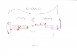
in one thread in the "Theory of Flight" section some basic questions regarding autorotation and autogyro flight had been asked. It occured to me that we have currently only fairly advanced material in our technical papers section. I would therefore like to invite everyone to post links to this thread where the most basic stuff - e.g. force diagram at a blade element with some explanation on how autorotation works - is well presented. I remember having seen some great stuff in the Rotary Forum so one idea would be to just post a link to stuff you have posted earlier to some thread of our forum. Please make this a great thread for those who take the first steps in understanding gyro flight!
 
Last edited:
Below to the right is the best diagram explaining auto rotation I have seen so far, from here:
https://faasafety.gov/gslac/ALC/course_content.aspx?cID=104&sID=452

The picture to the left from here:
http://aerofoilengineering.com/
makes it easy to understand why the resultant force on the profile is inclined forward with respect to the plane of rotation of the rotor. If you sum up all the blue arrows on the upper surface (and deduce the brown ones from below) you are left with a net force inclined forward (to the left) with respect to a horizontal line ( the plane of rotation of the rotor ). The angle of attack shown here is 5.5°. ( This by the way is exactly the same physics that allows a sailing boat to sail upwind )
 

Attachments

  • PressureDisplay.jpg
    PressureDisplay.jpg
    13.5 KB · Views: 6
  • Fig6-2.JPG
    Fig6-2.JPG
    41.1 KB · Views: 6
Last edited:
Wayne,

thanks for this very interesting link. I've so far only thought of the famous Horton "bell shaped" lift distribution to cope with pitch stability in flying wings. Quite amazing to learn they dealt with adverse yaw at the same time!
 
Hi guys.

I've read Greg's but thanks for posting all of them!!!!
 
A question, once again, based on this very basic diagram:
What‘s the physics behind the statements found here and there, that negative G lowers the rrpm considerably and even stops (besides chopping the tail) and that holding the stick into the wind after landing helps you to lower your rrpm faster?
Just trying to find a good, easy to understand, pedagogical formulation of explanation.
 
Last edited:
Just the basics.

Just the basics.

A question, once again, based on this very basic diagram:
What‘s the physics behind the statements found here and there, that negative G lowers the rrpm considerably and even stops (besides chopping the tail) and that holding the stick into the wind after landing helps you to lower your rrpm faster?
Just trying to find a good, easy to understand, pedagogical formulation of explanation.

Hello RT, it would help me to understand you question if you filled out you profile so I had a better idea of your experience and at least knew your name.

I don’t know what diagram you are referring to.

In my opinion with an autogiro the air going up through the rotor blades is what drives them; less air drives them less.

In my opinion as the blades move through the air there is aerodynamic drag that tries to slow the blades down.

When I fly with a passenger at a higher gross weight the rotor apears to turn faster.

When I fly at a higher density altitude the blades apear to turn faster.

My rotor tachometer confirms this impression.

I find that a low G maneuver makes for less air going up through the rotor and the drag slows the rotor quickly.

When I land and the rotor is not supporting the weight of the gyroplane it slows quickly.

I feel at that point the rotor sees zero Gs.

I don’t understand your second question.

I suspect it is the same answer. Less air going up through the rotor and the rotor slows.

Thank you, Vance
 
Last edited:
Hi Vance,
Thank you for trying to help me. My name is Roman, i‘m 48, live and fly in Sweden. I‘m still learning.
My questions are general and any try to answer them on any level would help me to try to find right way to explain my thoughts to my students.
I reffered to the picture of wing profile showing generated forces published in this thread.
In my world, there are no forces that could force rotor to stop when relative wind comes from above. The profile is not so effective when so, but significant braking force is something I can‘t see. Also, the fact that most rotors have blades with positive pitched profiles makes me believe that rotor can autorotate in same direction even when it "blows from above".
Both my questios are related to the same phenomena.
What I‘m trying to do is to modernize our theory material and erase the statements based on myths.
Regards,
Roman
 
Hello Roman,

What I am describing is about a low G maneuver that causes less air to come up through the rotor driving it and my observations as to the response of the rotor RPM.

Air flowing in the opposite direction is another thing entirely.

I am not an educated man so I am not be able to help you with theory and correct descriptive terms.

I am just offering my opinions and observations and they are often flawed.

Hopefully one of our more technically oriented forum members will help you.

Thank you, Vance
 
Also, the fact that most rotors have blades with positive pitched profiles makes me believe that rotor can autorotate in same direction even when it "blows from above".
It would probably autorotate alright but the rotor force would then be pointing downwards so the hole you leave in the ground on impact would be much bigger due to the added acceleration from the rotor force...;-)
The serious answer though is that your gyro would become highly unstable with the rotorforce pointing the wrong way round so you would tumble end over end in no time after flow direction has been reversed.
 
Last edited:
Hi Kolibri 282
Hehe, yes, The hole would be deeper.
I never said that lift would point upwards in negative G. I meant that there are no forces forcing the rotor to stop when negative loaded (besides usual drag).
Still, you can find statements here and there that negative G stops the rotor, as well as recommendations to hold the stick into the wind after landing in order to stop it faster.
The only test I have done was comapring times needed to stop the rotor. Horizontal in calm conditions vs. with stick induced flapping. The difference is considerable. Meaning of doing it was to get a feeling about how much increased flapping causes rotor to decrease in speed, the idea that apparently not all forum members share.

Roman
 
Last edited:
A question, once again, based on this very basic diagram:
What‘s the physics behind the statements found here and there, that negative G lowers the rrpm considerably and even stops (besides chopping the tail) and that holding the stick into the wind after landing helps you to lower your rrpm faster?
Just trying to find a good, easy to understand, pedagogical formulation of explanation.

IMHO, only drag is responsible for the deceleration of the rotor in both situations. Under negative Gs, and not taking into account very real problems of blades losing their 'rigidity', striking the fin and the prop; besides that, and for obvious reasons, you're not going to have enough time to build up enough airspeed 'in reverse' to aid the rotor to pull you to the hard ground...

And when you hold the stick into the wind, after landing, the disk is usually parallel to the flow of the wind, and thus only drag is at work...
 
Hey Fellas,

My 2 cents...

Any positioning of the blades, by pilot input, aircraft maneuvering, rigging, or any other way, THAT CREATES A TOTAL AERODYNAMIC FORCE VECTOR,TILTED REARWARD FROM THE ROTATIONAL AXIS WILL SLOW THE RPM.
 
This does not seem aligned with my experience.

This does not seem aligned with my experience.

Hey Fellas,

My 2 cents...

Any positioning of the blades, by pilot input, aircraft maneuvering, rigging, or any other way, THAT CREATES A TOTAL AERODYNAMIC FORCE VECTOR,TILTED REARWARD FROM THE ROTATIONAL AXIS WILL SLOW THE RPM.

Hello Brian,

I would be grateful if you would help me understand why you think; “Any Positioning of the blades, by pilot input, aircraft maneuvering, rigging or any other way, THAT CREATES A TOTAL AEROCYNAMIC FORCE VECTOR, TILTED REARWARD FROM THE ROTATIONAL AXIS WILL SLOW THE RPM.”

Thank you, Vance
 
Last edited:
You pose an interesting question Roman.

You pose an interesting question Roman.

Hi Vance,

In my world, there are no forces that could force rotor to stop when relative wind comes from above. The profile is not so effective when so, but significant braking force is something I can‘t see. Also, the fact that most rotors have blades with positive pitched profiles makes me believe that rotor can autorotate in same direction even when it "blows from above".
Both my questios are related to the same phenomena.
What I‘m trying to do is to modernize our theory material and erase the statements based on myths.
Regards,
Roman

Thank you for making your questions clearer to me Roman.

In my experience; in a low G maneuver the wind through the rotor disk does not reverse, it only slows.

I feel what the rotor system sees in a low G maneuver is a lighter gyroplane and that reduces the airflow up through the driven region of the gyroplane rotor.

The on the ground positioning of the disk seems all together different to me.

It seems possible to have the airflow coming from the top instead of underneath.

I had a rotor brake fail and had only limited success with this technique. The wind was not steady so this may have been a flawed example.

I had trouble with managing the blade tip path.

I usually just hold the disk flat as practical and when the rotor slows to 50 rotor rpm apply the rotor brake.

More experienced pilots than I have recommended this technique.

Thank you, Vance
 
Any positioning of the blades, ...... THAT CREATES A TOTAL AERODYNAMIC FORCE VECTOR,TILTED REARWARD FROM THE ROTATIONAL AXIS WILL SLOW THE RPM.
Edit/Delete Message
The rotor disk plane is perpendicular to the axis of rotation. In forward flight the net rotor force referred to the disk plane is always inclined backwards as the attached picture from the book of Harris shows (Harris p. 52). This corresponds to the formula for the H-force where the dominant term is 0.25*mu*delta, where delta is the average profile drag coefficient, which is always positive. A positive H-force by definition points to the opposite of the flight direction.

The rotor keeps spinning nevertheless since the net moment about the axis of rotation is zero. The next two pictures explain this fact.

The first one from the excerpt of the "Rotorcraft Flying Handbook" that Phillip has posted shows that the driving region on the retreating blade is larger than on the advancing. My little (very simplified) sketch shows the net forces on the rotor. Let us assume for simplicity that the brown region of the advancing blade drives the magenta region on the retreating blade. The brown region has to be larger since the lever arm of the magenta region is much larger. This leaves us with the large magenta region on the advancing blade whose decelerating moment is balanced by the (slightly larger) brown region on the retreating blade. So torque is balanced and the rotor keeps spinning. If we now sum the two regions below the blue line (brown to the left, magenta to the right, where the forces point to the rear of the aircraft) and deduce the two regions above the blue line we have a net H-force pointing to the rear.

Harris' book can be found here:
http://www.rotaryforum.com/forum/showthread.php?t=32431
 

Attachments

  • NetRotorForceHarrisPage52.png
    NetRotorForceHarrisPage52.png
    19.9 KB · Views: 2
  • GyroRotorDrivingAndDrivenRegions.png
    GyroRotorDrivingAndDrivenRegions.png
    17.7 KB · Views: 2
  • DrivingAndDrivenRegion.jpg
    DrivingAndDrivenRegion.jpg
    44.7 KB · Views: 2
Last edited:
The FAA publishes and excellent handbook - "Rotorcraft Flying Handbook" that covers both helicopter and autogyro technology, dynamics and flying.
It is available as a free pdf download from the FAA's web site.

Attached is an exert that deals with autogyro dynamics.
 

Attachments

  • autogyro dynamics.pdf
    102.6 KB · Views: 3
Simple

Simple

...help me understand why you think any positioning of the blades THAT CREATES A TOTAL AERODYNAMIC FORCE VECTOR, TILTED REARWARD FROM THE ROTATIONAL AXIS WILL SLOW THE RPM...

Air hitting the leading edge is trying to slow down the rotor.
Energy to keep that from happening HAS to come from somewhere.
That energy comes the total force vector (The net sum of all) being tilted forward of the rotation axis.
If anything is done to tilt that total force vector (The net sum of all) closer to the rotational axis, RPM will decay.
If it's (The net sum of all) tilted aft of the rotational axis RPM decays very rapidly.
 
Last edited:
Top