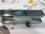
Brian's Genesis G1sa Build

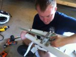
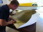
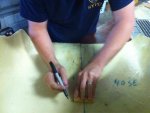
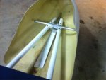
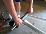
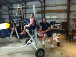
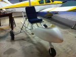
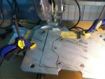
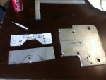
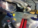
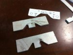
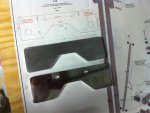
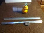
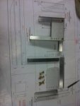
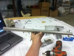
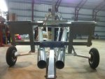
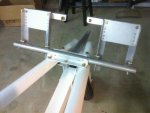
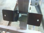
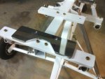
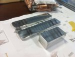
Tonight was fix stuff night. I had a rudder pedal support bracket that I wanted to square off better. I ordered some angle and fixed it tonight. After that, I secured the nose pod support bracket. Then I measured and cut the keel slot on the nose pod. Lastly, I made a seat mod and turned the Genesis into a three seater. Pics self explanatory. Good night.
 

Attachments

  • image-715887091.jpg
    image-715887091.jpg
    68.1 KB · Views: 2
  • image-79329949.jpg
    image-79329949.jpg
    76.2 KB · Views: 2
  • image-634584104.jpg
    image-634584104.jpg
    56.6 KB · Views: 2
  • image-1569090328.jpg
    image-1569090328.jpg
    74.1 KB · Views: 2
  • image-1085002470.jpg
    image-1085002470.jpg
    75 KB · Views: 2
  • image-3960691658.jpg
    image-3960691658.jpg
    62.1 KB · Views: 2
  • image-1510414740.jpg
    image-1510414740.jpg
    105.6 KB · Views: 2
  • image-1243760082.jpg
    image-1243760082.jpg
    87.9 KB · Views: 2
Lookin' good, Brian. I'll be back in Milton in a week. I'll get up with you so I can come check it out.
 
willisbr :Coming along pretty good....

Did you get the comment I made about using the cordless skill saw to cut the metal or have you found a better way..??????????
 
Last edited:
Worked on my engine mount plates today. I had a nice used plate from when I purchased the engine. So I traced out what I needed, saving as much as I could of the remaining plate.

The remaining challenge is trying to figure out how to cut out the inner area. Review the pics. Can someone give me an idea? Thanks
 

Attachments

  • image-829461094.jpg
    image-829461094.jpg
    76.7 KB · Views: 1
  • image-2253128685.jpg
    image-2253128685.jpg
    56.3 KB · Views: 1
  • image-228688342.jpg
    image-228688342.jpg
    85 KB · Views: 1
  • image-1643950917.jpg
    image-1643950917.jpg
    67.5 KB · Views: 1
Brian- first of all, you are doing a very nice job on your build. One way you could cut the bottom cut on your aluminum, I have set the saw fence on my table saw leaving the correct amount. Have the blade completely lowered , center the cut over the peak of the saw blade, turn the saw on and slowly raise the blade and saw to the angled corners. Check your cut several times and don't cut past the angles, of course! Flip it over and repeat. You then can take a saber saw and finish cutting. You can also use a carbide router , 1/2 inch shank with a pattern following bit to cut this instead of the table saw. A table saw can be used to make many notches and remove it that way. Or someone with a water jet could do it, but I am sure you are like me and want to do it yourself. Stan
 
Last edited:
Another few hours in the shop and the result was two engine mounts, ready for a few more holes and a final polish. These things were a pain in the mast.

I am going to be planning my instrument panel this week. I keep going back and forth between a few ideas. Trying to decide between full steam gauges, MGL digital gauges with combined indicators, or a small MGL EFIS such as the Enigma. Can't decide. Anyone have experience with these MGL products?

I'll be going with a Microair round transponder, and the XCOM or MGL radio.

Question: when one buys a transponder, do I need to also buy an encoder? What is the purpose of this? An MGL instrument I'm looking at has an encoding altimeter. Trying to figure out if this is helpful. Can someone please explain what I need to be looking for? Transponder is necessary for me as I live 1400 below class C. Thanks all.

Comments?
 

Attachments

  • image-1152953835.jpg
    image-1152953835.jpg
    73.8 KB · Views: 1
Question: when one buys a transponder, do I need to also buy an encoder? What is the purpose of this? An MGL instrument I'm looking at has an encoding altimeter. Trying to figure out if this is helpful. Can someone please explain what I need to be looking for?

Brian,

There are three modes of operation for typical general aviation transponders:

Mode A - Simply responds to being hit by the radar beam by transmitting a string of pulses encoded with your dial setting (the four digit number set by the panel knobs).

Mode C - Responds with the dial setting plus the pressure altitude (what your altimeter would read if always set to 29.92).

Mode S - Responds with all of the above plus an identifier unique to your aircraft registration for automatic ID on the controller's screen. (This code is assigned when you register the aircraft, and the number can be found on your aircraft's listing in the FAA database.)

For either C or S, your transponder needs to be fed a digital signal from an encoder connected to your pitot system's static port. The encoder is simply an altimeter which is permanently calibrated to 29.92, and creates a coded output signal instead of displaying on a meter face.

A "blind encoder" is just a little box which connects with a serial cable to your transponder.

An "encoding altimeter" is a single pressure sensor which drives both a meter face and the serial output. When you adjust the Kohlsman window in the altimeter to the actual local barometric pressure, it leaves the digital stream calibrated to 29.92.

Until recently, encoding altimeters were a more expensive solution than a separate blind encoder, but saved space. If you're equipping a panel from scratch, I'd guess you can get MGL's all-in-one encoding altimeter for less than a stand-alone altimeter plus a blind encoder.

Another advantage of the encoding altimeter is a better assurance of compliance with FAR 91.217, which requires your in-cockpit altimeter and the encoder feeding your transponder agree within 125 feet. Obviously, if they're fed off the same pressure sensor, slight changes in the sensor as it ages will affect both readings the same, keeping them in agreement.

Given their selling price and size, the MGL altimeters almost certainly use solid-state sensors, rather than an aneroid (bellows-type) sensor. At one time, the solid-state sensors were more troublesome to keep calibrated as they aged. That may not be a big deal anymore.

Some combinations of encoder and transponder require an adapter to translate the MGL's RS232 output to a different serial format the transponder can use.

Many gyroplanes have static ports located for convenience rather than accuracy. You'll need to make sure you've chosen a location for the port which is not affected by shadowing by the pod, etc. (If your altitude changes from standing still to rolling down the runway before takeoff, you got the wrong location.)
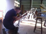
 
I'm not instrument whipped but I do have a few minimums engrained in my mind. I think I'll go with combined instrument options to save weight and real estate. Most likely, two or three MGL round units. I am located in between two surface class C radials so getting up and out is not just standard pasture flyin'. Lot's a military and airport opps within 10 miles. Plus I like reading. :)
 
Why not go with the MGL Enigma? It takes pitot and static pressures for altitude, speed and vertical speed info. Plus it displays all the engine parameters, fuel level and flow, compass heading and attitude, etc., etc. Plus it also has a great GPS built in, is highly user configurable (you like to read, right?). On MGL's website you also have a simulator for downlading that'll let you play with it on your PC just like the real thing.

-- Chris.
 
A lot for equipping a gyro perhaps, but for the money those are extremely sophisticated multifunctional units.

Certainly well worth thinking about for cross country touring machines.
 
I think the enigma is going to be excessive in price and feature for this application. I had originally considered it but I think I can do a more simple setup. I'll probably install my garmin 296 in the panel with the square bracket accessory.
 
Wow!!! Way to build Brian.
You have gotten a lot done is a very short time... Nice work buddy!

Also you might wish to check out Trig transponders!

http://www.trig-avionics.com/products.html

My aviation repair shop recommend Trig over Microair for my transponder!
 
How did you decide this? Trig is mode S only which I think is better than C?
Hi Brian!

The recommendation was based on the number of repairs seen in his shop as he felt they both preformed about the same. He also recommended the Flight Line FL-700 VHF Transceiver over the Microair which he see's much more often.

As to Mode S, yes Mode S transponders are compatible with Modes A & C.
Mode S (Selective) is designed to help avoiding overinterrogation of the transponder (having many radars in busy areas) and to allow automatic collision avoidance.
This is the transponder that makes the ACAS II (Airborne Collision Avoidance System) and the ADS-B (Automatic dependent surveillance-broadcast) systems function.
 
The only thing worse than waiting on parts is getting home with a note stuck to the door that says we tried to deliver but your not home. Now my parts sit lonely down the street in a dark warehouse until tomorrow. Poor lonely parts. All alone out there in the world. I need you parts. Come home to me.
 
Got some angle and bar in this week. Going to redo some brackets, a rudder pedal, and make a deposit into the bucket of shame toniggt. I still have a left rudder pedal for sale... :)
 

Attachments

  • image-3344850564.jpg
    image-3344850564.jpg
    101.8 KB · Views: 0
I spent the last two nights cutting, sanding, and polishing some new brackets. Finished the rudder pedals. I now have pedals for BOTH feet :)

I'm remaking the suspension forward strut brackets because I was not pleased with my alignment. Ever since I got some better drill bits I have had no problems with alignment. Tonight I will be finishing these last brackets pictured.

Enjoy the pics. Going out for some Mexican. Good night.
 

Attachments

  • image-1059688459.jpg
    image-1059688459.jpg
    51.9 KB · Views: 2
  • image-1454320371.jpg
    image-1454320371.jpg
    77.4 KB · Views: 2
  • image-3718285412.jpg
    image-3718285412.jpg
    87 KB · Views: 2
  • image-3049278670.jpg
    image-3049278670.jpg
    77.2 KB · Views: 2
  • image-4088880147.jpg
    image-4088880147.jpg
    66.6 KB · Views: 2
  • image-1979753277.jpg
    image-1979753277.jpg
    77.1 KB · Views: 2
  • image-373568531.jpg
    image-373568531.jpg
    62.9 KB · Views: 2
  • image-1519393494.jpg
    image-1519393494.jpg
    62 KB · Views: 2
Top