FFT Magni rotor Vibration analysis

Most people don’t spend a lot of time worrying about the resonator bars in a Glockenspiel, Mike. Only Glockenspiel designers would.

The same is true for rotors. Most likely, the only person, if any, to have thought about Magni rotor resonances was Jukka Tervamaki.

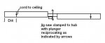
Your lower sketch is the one.
 
Chuck
I'm going to take the rotor off the Magni in June to transport it to Brittany and if I find the time I'd like to try your method to for the in plane natural frequency (static). So could you confirm how you hung the rotor and in what direction the jigsaw was reciprocating.
Mike G
 
Here’s the setup I used, as nearly as I can remember; it’s been 20 years. I recall chucking a short length of steel rod to the saw plunger.

The magnetic pickup was a Chrysler variable reluctance ignition pickup sensing plunger motion, driving an electronic counter set to measure period.

The saber saw was driven from a variable voltage transformer, a Variac.

The weight of the saw lowers frequency somewhat.

Interestingly, I clamped the rotor turned edgewise in a milling machine and measured droop at the tips, using a water level. The calculated resonant frequency of the free mode agreed quite closely with my measured result. Formulae are tabulated in most any mechanical engineering handbook.
 

Attachments

  • shaker.JPG
    shaker.JPG
    7.2 KB · Views: 4
Chuck your sketch is a plan view right?
Mike G
 
Thanks
I've been playing with my balancer using a simple test rig (my elecric drill chucked to a bolt going through the middle of a length of wood. I'm not getting coherent readings of angle in balance mode so I'm going to talk to the balancer maker again tomorrow.
Mike G
 
Mike,

Just wanted to let you know that I got similar results on a MTO Sport using a DSS Microbalancer. I measured both lateral and vertical vibration just below the head.

1 per rev:
Lateral: Less than 0.1 ips
Vertical: Less than 0.1 ips

2 per rev:
Lateral (low speed): Between 1.5 and 2 ips
Lateral (60mph): 2 ips
Lateral (100 mph): 4 ips
Vertical: More than 1 ips

I did some vertical measurements with the sensor at the pilot seat as well, they were in the same ball park as at the head.

It's good to see that 2 per rev vibration is generating some interest. The average pilot cannot really do much about it (except fly slower) but a better understanding of it is bound to result in safer and more durable aircraft.

Oskar
 
Chris how do you know which blade needs to have the pitch changed?
Mike
 
Oskar
How do you know that you are measuring 2/rev vibration with the Microbalncer?
Mike
 
Oskar
How do you know that you are measuring 2/rev vibration with the Microbalncer?
Mike

You'd have to rig it so that the rpm sensor (photo diode) receives 2 signals per revolution. Simply stick a reflective tape 180° apart at whatever part you use to measure rpm. I used the prerotator gear.

-- Chris.
 
Chris
Is that in the manual or is that just how you do it? Do you have an electronic version of the manual, I'd like to understand more about what the Microbalancer is capable of.
I think that if you put two reflective tapes on you would fool the balancer but maybe they have a way around this.
Mike G
 
Chris when you measure the vertical vibration does the Micrbalancer give you a vibration (mm/s or IPS) and a an angle?
Mike G
 
Mike, the trick with the 2 pieces of reflective tape is mine and not in the manual. It will work but you have to be careful interpreting the resulting angle. There will be ambiguity introduced since 6 and 12 o' clock are now indistinguishable to the unit.

The microbalancer gives me IPS for both horizontal and vertical orientation of the accelerometers.

BTW, it'll result in a more sensitive setup if you mount the vertical accelerometer far away from the CoG. That's why I had it forward near the pilot seat.

-- Chris.
 
Chris
Interesting, I'm off to the USA for a week, will get back to you when I return. I thought about the double reflecting tape thing again today, you're probably right since the balancer filters the vibration to the frequency it thinks is the rotating frequency.
I'd still like to see a manual for your Microbalancer, I'm not happy with what I'md oing and am looking for an alternative.
Mike G
 
Mike,

Chris is correct, to measure 2 per rev you need to add a second position signal 180 degrees out of phase.

Just a few comments on the Microbalancer. I've reverse engineered one and have found that some parts of it are extremely good while other parts are not good.

The weak points are:
- The optical sensor is not good (especially outdoors), I only use magnetic sensors.
- The DSS only works properly if the rpm is kept constant, too fast changes in rpm cause erratic readings.

Oskar
 
Oscar,

it took a bit to get the optical pickup of the rpm sensor working but then it didn't show any problems or glitches. I used the supplied reflective tape and stuck it to the prerotator gear. The optical head was about 1-2 inches below it, if I remember correctly.

What I liked was that the DSS was extremely simple to use. It gives you one reading (IPS and phase angle) and averages it, if you ask it to do so. It seemd to work reliably.

Regarding your quickly changing rpm and associated problem I can't comment because I didn't observe it. Maybe that's more of a problem if you are balancing the prop with it? Rotors don't tend to change their rpms that quickly due to their high rotational inertia in comparison with the rate of change in aerodynamic driving moments.


-- Chris.
 
What in the World is an FFT (fast Fourier transform)?

Jean Fourier was a French mathematician who around 1800 discovered that any arbitrary waveshape was made up a fundamental frequency plus harmonics (overtones). That’s the reason the same musical note sounds so different between various musical instruments; overtone content.

Rotor shake is rarely a pure sinewave (no harmonics). That’s where Mr. Fourier comes in; we use his methods to resolve a wave into its constituent parts.

A triangular wave is made up of fundamental plus even harmonics.

A square wave is made up of fundamental plus odd harmonics. I’ve plotted the beginning of a squarewave using fundamental, 3rd harmonic and 5th harmonic. Perfection would require odd harmonics extending to infinity.
 

Attachments

  • FFT.JPG
    FFT.JPG
    16.5 KB · Views: 0
What in the World is an FFT (fast Fourier transform)?

Chuck, an FFT (Fast Fourier Transform) is a particularly clever computer algorithm to perform a Fourier Transform. If you performed a Fourier Transform the way a mathematician would (using integrals over products of wave functions), a computer would take forever to get it done. So that's why being clever and getting a darn good approximation to the real thing that calculates orders of magnitudes faster is so useful.

-- Chris.
 
Top