A new direction

gyrojake

Gyro Rehab Candidate
Joined
Jan 1, 2007
Messages
2,313
Location
E-City, Florida
Aircraft
Gyroplanes
Total Flight Time
A few hours
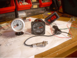
Well I just spent my vacation money for a few years !! I bought a 1ghz (one gigahertz) Oscilloscope and a 4.7ghz RF spectrum analyzer.
I think I'm getting out of gyro building and start making wireless engine monitoring systems.
These tools are a must for my future endeavors.
I amazed myself with the wireless rotor tach and think this new project will be challenging and rewarding.
Now I gotta go burn one and wake up my last brain cell so I can accomplish this.
I will have to learn coding and hexadecimal programing for this adventure.
I guess we never stop learning if motivated properly.
Oh, and by the way, I will have this learned tonight !!
 
If you have this learned by tonight I'm sure it's because you already know it and just need to refresh you skills.
I know a bit of this I was a radio Operator for 25 years.

But don't stop building Gyro's your good at it. if I had the cash I would make you build me a yamaha powered one.
 
Nice gear Jake!

One of the microprocessor-controlled knees I work on was originally introduced in the mid-90s, when memory was still costly enough that they used hexadecimal to avoid wasting any precious bits. I had to dust off some brain cells that had been snoozing since the '80s to learn to talk to that product.

Trouble is, none of the songs they teach kids to help them learn to count go all the way up to F!
 
Rotor tachometer wireless is good.
On my side I just made my own rotor tachometer with wires, designed for a crown of 10 magnets
1 box recovered from a broken board instrument
1 Chinese car tachy (for his galvanometer): 10$
1 Chinese digital tachy (for calibration) + sensor : 10$
Few electronic components : 5$
New scale printed from a Google image

Sans titre.png
 
PW_Plack;n1131636 said:
Nice gear Jake!

One of the microprocessor-controlled knees I work on was originally introduced in the mid-90s, when memory was still costly enough that they used hexadecimal to avoid wasting any precious bits. I had to dust off some brain cells that had been snoozing since the '80s to learn to talk to that product.

Trouble is, none of the songs they teach kids to help them learn to count go all the way up to F!

My new project will be using Pic microcontrollers that use a hex file.
It will have a 16 channel bus output to integrate all of the engine monitoring components.
I will be able to modulate all inputs on one RF frequency and the receiver will be able to differentiate and send each probe to the required input of the EIS ( engine information system )
Each input is sampled at .1 microsecond, so this is actually faster than the update time of the EIS.

The Oscilloscope is Awesome, it is the fastest real time O-Scope I've ever used and has the most sensitive input from x10 to x5k..
It has an auto mode which plots unknown frequencies and voltages that i do not have to preset.
It also does Zoom + Math, which will give me a comprehensive view of my traces in four perspective levels.
The only drawback is the active probes are 900 bucks each and the price of the scope could have bought me a nice car.

The Avcom Spectrum analyzer is an older device, but never used and the trace and modulation depiction is beautiful.
My home built one was Ok. but only went to 1ghz.
 
Jean Claude;n1131638 said:
Rotor tachometer wireless is good.
On my side I just made my own rotor tachometer with wires, designed for a crown of 10 magnets
1 box recovered from a broken board instrument
1 Chinese car tachy (for his galvanometer): 10$
1 Chinese digital tachy (for calibration) + sensor : 10$
Few electronic components : 5$
New scale printed from a Google image


Very nice.
I have a wireless system that will work with the hall effect sensor you are using.
I designed a system for that Chinese tach, Red Lion tach and the MGL tack.
I'm working on an analog wireless tach system now and when complet Vance Breeze will test it out for me.
Next is a wireless engine monitoring system.
 
gyrojake;n1131643 said:
I'm working on an analog wireless tach system now
Nice.
Does the transmitter work on batteries?
Does it have a power switch?
 
Last edited:
I designed a digital rotor tach ~30 years ago using standard ICs for which Ken Brock had a small job shop build a pc board and housing, listing it in his catalog for a number of years.

I personally dislike digital displays; can’t stand blinking digits.

Analog displays using instrument galvanometers were too fragile for use on a gyro powered by a vibrating McCulloch.

My favorite rotor tachs used a 0-50 mph motor scooter speedometer and a standard automobile drive cable housed in vinyl tubing, driven by gears at the rotorhead. Some automotive shops had speedometer drive cable in spools and would make up whatever length desired with swagged on terminations.
 
Last edited:
C. Beaty;n1131656 said:
I designed a digital rotor tach ~30 years ago using standard ICs for which Ken Brock had a small job shop build a pc board and housing, listing it in his catalog for a number of years.

I personally dislike digital displays; can’t stand blinking digits.

Analog displays using instrument galvanometers were too fragile for use on a gyro powered by a vibrating McCulloch.

My favorite rotor tachs used a 0-50 mph motor scooter speedometer and a standard automobile drive cable housed in vinyl tubing, driven by gears at the rotorhead. Some automotive shops had speedometer drive cable in spools and would make up whatever length desired with swagged on terminations.

I agree...even clocks. Glancing at an analog face gives an instant impression rather than the thought that is necessary with a digital display.

smiles,
Charles
 
C. Beaty;n1131656 said:
I designed a digital rotor tach ~30 years ago using standard ICs for which Ken Brock had a small job shop build a pc board and housing, listing it in his catalog for a number of years.

I personally dislike digital displays; can’t stand blinking digits.

Analog displays using instrument galvanometers were too fragile for use on a gyro powered by a vibrating McCulloch.

My favorite rotor tachs used a 0-50 mph motor scooter speedometer and a standard automobile drive cable housed in vinyl tubing, driven by gears at the rotorhead. Some automotive shops had speedometer drive cable in spools and would make up whatever length desired with swagged on terminations.

Hahaha!! In 1988 the fastest computer processor was an 8088 and most IC's were analog audio.
In 1970 Fairchild .introduced the first operatible C-Mos and by 1988 was the 8088 which was only 5mhz max with an 8mhz clock.
Today I use anywhere from 100mhz to 1ghz for a clock.
Today's technology offers speeds in milli and microseconds not seconds and half seconds.
The products on the market today are using 90's technology and that's why they are so slow at the .5 second update or more.
The cost of redesign to them is not worth it because they are selling without question.
I'm sure your L.E.D. tach was the best for it's time and the up date time was in seconds.
By no doubt analog is the fastest response, but with the new P.I.C. microcontrollers your eye will never notice the difference.
It is easier for the mind to watch a needle move in a linear fashion, but anything faster than 30hz in change you will never notice anyway, to you it would be instantaneous.
As anything it's what your mind can comprehend and process.
I use to use a bicycle wheel rub alternator on my ring gear and a bicycle speedo recalibrated, but today I'm going with the high tech redneck solution, and that's only because I can.
 
Last edited:
Jean Claude;n1131653 said:
Nice.
Does the transmitter work on batteries?
Does it have a power switch?

My 108 tooth count needs no external power or battery.
Your set up will need power for the hall effect transistor and that could also power the transmitter.
If you have to run wires for any part of the tach I see no reason for a wireless transmitter.
Now I could build one that uses your crown of magnets as an alternator and modulator at the same time and you will not need wires.
Get rid of the hall effect and use a inductive reactor and then it will be totally wireless with no batteries or external power for the transmitter.
The receiver will need power from the regulator or battery.
Or use your 108 tooth ring gear and it will be plug and play.
 
I used a long chain binary divider programed to divide the 32768 quartz clock oscillator down to 9 pulses/second, then selected 5 pulses to generate a 5/9 second count window. Counting pulses from the 108 tooth ring gear with a 5/9 second count window gives 5/9 x 108 = 60 which for 1 rev/sec = 60 rpm.
No need to mess around with the kind of electricity that runs through pipes (waveguides) rather than along wires when counting pulses from prerotator ring gears.

I still have a schematic if you’d like a copy.
 
Last edited:
C. Beaty;n1131677 said:
I used a long chain binary divider programed to divide the 32768 quartz clock oscillator down to 9 pulses/second, then selected 5 pulses to generate a 5/9 second count window. Counting pulses from the 108 tooth ring gear with a 5/9 second count window gives 5/9 x 108 = 60 which for 1 rev/sec = 60 rpm.
No need to mess around with the kind of electricity that runs through pipes (waveguides) rather than along wires when counting pulses from prerotator ring gears.

I still have a schematic if you’d like a copy.

For the day that was awesome.
I understand and have some programmable dividers that I used on obsolete PLL's.
I would like the schematic for educational purposes and the part numbers.
I feel the RF doesn't have a wire whippin in the wind and can't lose a connection and stop working.
I don't even use a rotor tach I see no use for one since like you, learned in a bare bones machine.
I don't use waveguides, only a radiator and an oscillator, no need for waveguides.
I also use an inverted A.S.K. modulation which gets information at the ground line so no heterodyning or interference can corrupt the information.
The zero part of the square wave is the information where nothing is happening.
But I do love to experiment and come up with a new twist now and then.
No one else has done it and I feel it is a personal accomplishment, but some demean the idea because they do not truly understand.
Do you have a wire on your cell phone? You do have waveguides and duplexers though.
 
I‘ve tinkered with high speed stuff a bit but am not convinced its here to stay:

https://patents.google.com/?inventor=Charles+A+Beaty&oq=Charles+A+Beaty
 
C. Beaty;n1131685 said:
I‘ve tinkered with high speed stuff a bit but am not convinced its here to stay:

https://patents.google.com/?inventor=Charles+A+Beaty&oq=Charles+A+Beaty

VERY NICE, but innovations of existing technology of the day, people are still getting patents on the same devices.
Here is the same product from Raytheon Co in 2000 https://patents.google.com/patent/US7590401, maybe you should sue them.
Anyway, nice accomplishments, unless you owned the company and claimed the research as yours, that has happened to me before as an employee.
 
gyrojake;n1131676 said:
If you have to run wires for any part of the tach I see no reason for a wireless transmitter.
Of course but I was thinking to integrated batterie, like "Tiny-Tach"

In my opinion reading a digital signage takes too much time to be decoded by our brain. Decryption of the signs, mental representation of 3 signs in base 10, several repetition of this process for the watching of variation slope. This usually takes few precious seconds of attention to the pilot.
Could you not light a virtual needle?
 
For me, rotor start was much easier to manage with an analog display of rpm.

My guess is that some destructive flapping during rotor start could be avoided if analog rather than digital display was used.

Critical aircraft instruments, airspeed, altitude, engine rpm, etc are always analog for the reason JC has explained above.

Long live the steam gauge!
 
Last edited:
Jean Claude;n1131697 said:
Of course but I was thinking to integrated batterie, like "Tiny-Tach"

In my opinion reading a digital signage takes too much time to be decoded by our brain. Decryption of the signs, mental representation of 3 signs in base 10, several repetition of this process for the watching of variation slope. This usually takes few precious seconds of attention to the pilot.
Could you not light a virtual needle?

Yes, you could use a battery
You could also use the power from the sensor.
The interface with the analog tach is on my work bench now and should be complete in a few days.
 
C. Beaty;n1131698 said:
For me, rotor start was much easier to manage with an analog display of rpm.

My guess is that some destructive flapping during rotor start could be avoided if analog rather than digital display was used.

Critical aircraft instruments, airspeed, altitude, engine rpm, etc are always analog for the reason JC has explained above.

Long live the steam gauge!

I agree and understand completely, I stated that in my post.
Analog gauges are faster to comprehend.
You can't buy an analog rotor tach unless you modify an existing product.
Most Aircraft today use a digital E.I.S, such as Grand Rapids, MGL and Datcom.
Most common Rotor Tachs are Red Lion and MGL.
I am going to cover both fields but started with the digital first .
The wireless Analog on the receiving end is a bit more sophisticated than digital.
In my experiment, analog tachs perform better with a pure clean sign wave, A.S.K. doesn't work as well.
Now I have to make two different receivers, one digital and one analog.
The analog gauges I am going to have produced will be oil filled so vibration will not be an issue and will have the same response time as air.
What you and I like does not have an effect on the new market, so I'll follow the market till there is a bigger demand on analog devices.
I'am proceeding with the analog rotor tach,everything else will be digital..
 
gyrojake;n1131675 said:
Today's technology offers speeds in milli and microseconds not seconds and half seconds.
By no doubt analog is the fastest response, but with the new P.I.C. microcontrollers your eye will never notice the difference.
The problem of digital signage comes from our brain, and not from the electronic low speed. Thus, today's fast technology will not improve it.
Your wireless transmitter powered by the gearwheel as an alternator is a good thing.
In my experiment, analog tachs perform better with a pure clean sign wave, A.S.K. doesn't work as well.
Why not a DC current? My simplistic schema.:
Sans titre.png
 
Last edited:
Top