and triple the price of Leon Gyro - scandal :rant:The Carbon Cub is also more than double the price of an MTO.
You are using an out of date browser. It may not display this or other websites correctly.
You should upgrade or use an alternative browser.
You should upgrade or use an alternative browser.
gyrocopter REVO
- Thread starter TNVD
- Start date
Hello to all,
My name is Christophe Caumette. I am the designer of the autogiro Revo. I am sorry for the name and the resemblance with existing devices. I am only a builder amateurs and I reassure the professionals, there is no question to market this device.
The conception in begun in January, 2012 and I copied nobody. The idea to add fixed wings to our machines to improve the performances is known of all, certain prototypes of "convertible" date the 50s. I invite you to consult the site https: // sites.google.com / site / autogirerevo / to understand the approach and the stages of the conception. Everything is explained except the head of rotor and its system of automatic variable step according to the loader (wings support until 50 % of the load).
Thank you in advance for your constructive comments.
Friendly
Panpan
Smack
Re-member?
- Joined
- Nov 3, 2013
- Messages
- 935
- Location
- Georgetown
- Aircraft
- Kitfox IV / F1 Rocket / Magni M-16 / Beech 18 / Aviomania G2sA-2
- Total Flight Time
- 550+
add detail
add detail
Christophe, is there an English-language version?
Also, please describe the rotorhead and what you mean about it changing pitch after some % of the load is shared by the wing.
Any more progress photos? I like it !
Brian
add detail
Christophe, is there an English-language version?
Also, please describe the rotorhead and what you mean about it changing pitch after some % of the load is shared by the wing.
Any more progress photos? I like it !
Brian
All_In
Gold Supporter
- Joined
- Apr 21, 2008
- Messages
- 16,105
- Location
- San Diego, CA. USA
- Aircraft
- Airgyro AG915 Centurian, Aviomania G1sb
- Total Flight Time
- Gyroplane 70Hrs, not sure over 10,000+ logged FW, 260+ ultralights, sailplane, hang-gliders
Wow that looks sweet!!!
I'm very interested in your project glad I found it!!!
Any updates?
I'm very interested in your project glad I found it!!!
Any updates?
Hello,
(Sorry for the bad translation, I do not write English).
Thank you Abid for the compliment.
Brian,
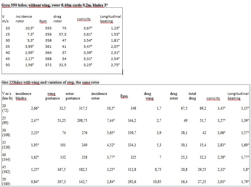
The wing generates an important portance, capable of supporting, in high speed, more than half weight of the machine and his pilot. Without variation of blades pitch, the rotor would slow down dangerously provocating an exaggerated beating. The mechanical and automatic system (without intervention of the pilot) allows this variation, proportionally in the load :
Gyro 350 kilos, without wing, rotor 8,40m cords 0,2m, blades pitch 3°
Vm/s pitch Rpm drag conicity beating
rotor rotor
20 10,5° 355 75 3,67° 1,23°
25 7,3° 356 57,3 3,61° 1,53°
30 5,3° 358 47 3,54° 1,81°
35 3,95° 361 41 3,47° 2,07°
40 2,95° 364 37 3,39° 2,31°
45 2,17° 368 34 3,31° 2,54°
50 1,56° 372 32,5 3,23° 2,75°
Giro 350kilos with wing and variation of blades pitch, the same rotor
V m/s pitch portance portance pitch Rpm wing rotor total conicity beating
(km/h) blades wing rotor rotor drag drag drag
20(72) 2,66° 32,5 317,5 10,5° 348 1,7 67,5 69,2 3,45° 1,15°
25(90) 2,47° 51,25 298,75 7,44° 344,2 2,7 49 51,7 3,27° 1,39°
30(108) 2,23° 74 276 5,65° 339,7 3,9 38,1 42 3,06° 1,57°
35(126) 1,95° 101 249 4,52° 334,1 5,3 30,1 35,4 2,83° 1,69°
40(144) 1,62° 132 218 3,77° 325 7 25,3 32,3 2,58° 1,77°
45(162) 1,25° 167,5 182,5 3,25° 312,8 8,75 20,8 29,55 2,32° 1,8°
50(180) 0,84° 207,3 142,7 2,84° 292,6 10,85 16,4 27,25 2,03° 1,79°
John,
The construction little progressed since the creation of the web site. The tries are planned in 2016, I hold you informed.
Christophe
(Sorry for the bad translation, I do not write English).
Thank you Abid for the compliment.
Brian,
The wing generates an important portance, capable of supporting, in high speed, more than half weight of the machine and his pilot. Without variation of blades pitch, the rotor would slow down dangerously provocating an exaggerated beating. The mechanical and automatic system (without intervention of the pilot) allows this variation, proportionally in the load :
Gyro 350 kilos, without wing, rotor 8,40m cords 0,2m, blades pitch 3°
Vm/s pitch Rpm drag conicity beating
rotor rotor
20 10,5° 355 75 3,67° 1,23°
25 7,3° 356 57,3 3,61° 1,53°
30 5,3° 358 47 3,54° 1,81°
35 3,95° 361 41 3,47° 2,07°
40 2,95° 364 37 3,39° 2,31°
45 2,17° 368 34 3,31° 2,54°
50 1,56° 372 32,5 3,23° 2,75°
Giro 350kilos with wing and variation of blades pitch, the same rotor
V m/s pitch portance portance pitch Rpm wing rotor total conicity beating
(km/h) blades wing rotor rotor drag drag drag
20(72) 2,66° 32,5 317,5 10,5° 348 1,7 67,5 69,2 3,45° 1,15°
25(90) 2,47° 51,25 298,75 7,44° 344,2 2,7 49 51,7 3,27° 1,39°
30(108) 2,23° 74 276 5,65° 339,7 3,9 38,1 42 3,06° 1,57°
35(126) 1,95° 101 249 4,52° 334,1 5,3 30,1 35,4 2,83° 1,69°
40(144) 1,62° 132 218 3,77° 325 7 25,3 32,3 2,58° 1,77°
45(162) 1,25° 167,5 182,5 3,25° 312,8 8,75 20,8 29,55 2,32° 1,8°
50(180) 0,84° 207,3 142,7 2,84° 292,6 10,85 16,4 27,25 2,03° 1,79°
John,
The construction little progressed since the creation of the web site. The tries are planned in 2016, I hold you informed.
Christophe
Jean Claude
Junior Member
- Joined
- Jan 2, 2009
- Messages
- 2,599
- Location
- Centre FRANCE
- Aircraft
- I piloted gliders C800, Bijave, C 310, airplanes Piper J3 , PA 28, Jodel D117, DR 220, Cessna 150, C
- Total Flight Time
- About 500 h (FW + ultra light)
Hello Christophe
The European builders are unable to comply with the french regulatory limit of 450 kg and claim 100 kg extra . If you obtain 350 kg, then they will be ashamed of their bad aircraft design.
The European builders are unable to comply with the french regulatory limit of 450 kg and claim 100 kg extra . If you obtain 350 kg, then they will be ashamed of their bad aircraft design.
Bonjour Jean-Claude,
Le poids énoncé de 350kgs s'entend pilote à bord. Le poids de la machine devrait être de 270/280kgs, les projections à ce stade de la construction sont conforme à cet objectif.
Au delà de 350 kgs, le système atteint sa butée haute et verrouille le pas à 3°.
(The weight expressed of 350kgs gets on pilot on board. The weight of the machine should be of 270 / 280kgs, the projections at this stage(stadium) of the construction are in accordance with this objective.
Beyond 350 kg, the system reaches its high abutment and locks the pitch in 3 °.)
Christophe
Jean Claude
Junior Member
- Joined
- Jan 2, 2009
- Messages
- 2,599
- Location
- Centre FRANCE
- Aircraft
- I piloted gliders C800, Bijave, C 310, airplanes Piper J3 , PA 28, Jodel D117, DR 220, Cessna 150, C
- Total Flight Time
- About 500 h (FW + ultra light)
Oups, Je croyais 350 kg avec deux passagers à bord, comme vous montrez ici: https://sites.google.com/site/autogirerevo/
Pour un monoplace, la règlementation française ULM limite la masse totale à 300 kg.
(Oops, I thought 350 kg with two passengers on board, as you show here:
https://sites.google.com/site/autogirerevo/
For a single seater, ULM French regulations limit the total mass of 300 kg.)
Pour un monoplace, la règlementation française ULM limite la masse totale à 300 kg.
(Oops, I thought 350 kg with two passengers on board, as you show here:
https://sites.google.com/site/autogirerevo/
For a single seater, ULM French regulations limit the total mass of 300 kg.)
Jean-Claude,
Il s'agit bien d'un biplace ("intime", sans double commande). Merci pour ces rappels sur la règlementation. 350kg, c'est la limite haute fixée pour la variation de pas.
It is well about a two-seater ("close friend", without double command). Thank you for these reminders on the regulations. 350kg, it is the high limit fixed for the variation of pitch.
Jean Claude
Junior Member
- Joined
- Jan 2, 2009
- Messages
- 2,599
- Location
- Centre FRANCE
- Aircraft
- I piloted gliders C800, Bijave, C 310, airplanes Piper J3 , PA 28, Jodel D117, DR 220, Cessna 150, C
- Total Flight Time
- About 500 h (FW + ultra light)
Merci. Je comprends maintenant.
Puisque vous conservez un angle de 3 ° pour l'aile fixe, cela nécessite un grand changement de l'angle pour le disque rotor en fonction de la vitesse de vol, et une poussée de rotor se déplaçant par rapport au centre de gravité. L'empennage horizontal doit équilibrer ces changements de couple. Cela suppose une portance et une trainée d'équilibrage qui mériteraient peut être d'apparaître dans votre table.
Pour limiter les déséquilibres, il me semble que l'aile devrait être plus avancée.
(Since you keep an angle of 3 ° for the fixed wing, this requires a large changing of angle for the rotor disk depending on the speed of flight, and its rotor thrust moving relatively to the center of gravity. The horizontal tail must balance these changing torques. This assumes a lift and a balancing drag which should appear in your table.
To reduce the imbalances, it seems to me that the wing should be more advanced.)

Last edited:
Bonjour Jean-Claude,
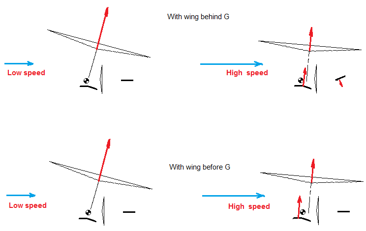
En effet, comme sur tous autogire, l'assiette de la cellule change avec la vitesse (inclinaison du rotor, trainée de la cellule et du rotor inversement proportionnelle). C'est pour cette raison que l'incidence de l'empennage est modifiable en vol, au détriment d'une trainée supplémentaire (Je crois que Carter Copter fait varier la position du mât). Reste à voir si un un compromis sur sa position est possible. .
J'ai choisi de positionner le foyer de l'aile fixe en arrière du centre de gravité pour privilégier la stabilité en tangage à toutes les vitesse.
Indeed, as on all autogiro, the plate of the cell changes with the speed (slope of the rotor, dragged by the cell and by the rotor inversely proportional). This is why the incidence of the empennage is modifiable during flight, to the detriment of an additional trail (I believe that Carter Copter makes vary the position of the mast).
I chose to position the home(foyer) of the fixed wing at the back of the center of gravity to favor the stability tanguage in all speed.
Jean Claude
Junior Member
- Joined
- Jan 2, 2009
- Messages
- 2,599
- Location
- Centre FRANCE
- Aircraft
- I piloted gliders C800, Bijave, C 310, airplanes Piper J3 , PA 28, Jodel D117, DR 220, Cessna 150, C
- Total Flight Time
- About 500 h (FW + ultra light)
In this case, to 50 m/s and 350 kg:I chose to position the aerodynamic center of the fixed wing at the back of the center of gravity to favor the stability tanguage in all speed.
The lift of the wing produces a moment about 100mN, nose down (because back two inches)
The Cm0 of the wing produces a moment about 370mN, nose down (because Cm= 0,1)
The lift of the rotor produces a moment about 370mN, nose down (because 10° less relatively to airframe)
The total 840 mN requires a tail lift of 470 N down (if tail rear 6 ft
It's just a comment, but I'm sure you have already taken this into account.
Tout d’abord, merci pour l’intérêt que vous portez à mon projet. Je vous est beaucoup lu par ailleurs et vous y avez, en quelque sorte, participé.
Concernant vos calculs sur l’empennage, pourriez-vous, à titre de comparaison, calculer les effets produit sur celui d’un autogire sans aile, son rotor supportant la totalité de la charge (350 kg au lieu de 150 kg), pour maintenir son équilibre à la même vitesse ?
Christophe.
First of all, thank you for the interest to my project. I is besides read a lot to you and you participated in it, in a way.
Concerning your calculations on the empennage, could you, as comparison, calculate the effects product on that of the autogiro without wing, its rotor supporting(bearing) all of the load(responsibility) (350 kg instead of 150 kg), to maintain his(her,its) balance in the same speed?
Christophe.
Jean Claude
Junior Member
- Joined
- Jan 2, 2009
- Messages
- 2,599
- Location
- Centre FRANCE
- Aircraft
- I piloted gliders C800, Bijave, C 310, airplanes Piper J3 , PA 28, Jodel D117, DR 220, Cessna 150, C
- Total Flight Time
- About 500 h (FW + ultra light)
L'équilibre longitudinal d'un autogire sans ailes est obtenu pour toutes valeurs de force sur l'empennage, grâce au changement d'assiette de la structure.Concerning your calculations on the empennage, could you, as comparison, calculate the effects product on that of the autogiro without wing, its rotor supporting(bearing) all of the load(responsibility) (350 kg instead of 150 kg), to maintain his(her,its) balance in the same speed?
Si vous acceptez ce changement d'assiette de la structure, alors aucune force d'équilibrage par l'empennage n'est requise.
The longitudinal balance of a wingless autogyro is obtained for any force values on the tail, thanks the airframe attitude change.
If you accept this airframe attitude change, then no balance required by the tail.

Last edited:
Nous sommes d’accord pour dire qu’aucune force sur l’empennage n’est nécessaire pour maintenir l’équilibre. C’est la valeur de la force qui s’exerce à ces vitesses, sur l’empennage au calage fixe de l’autogire classique, qui m’intéressais de comparer avec celle nécessaire à maintenir la structure en ligne de vol.
La structure traîne davantage et on peut noter que la direction de la force de propulsion, dirigée vers le bas, doit être contré.
We agree to say that no strength on the empennage is necessary to maintain the balance. It is the value of the strength that practices(is applied) these speeds, on the empennage in the fixed wedging of the classic autogiro, which interested me to compare with that necessary to maintain the on-line structure of flight(theft).
The structure is more lying about(dawdles) and we can note that the direction(management) of the strength of propulsion, managed downward, must be countered.
Jean Claude
Junior Member
- Joined
- Jan 2, 2009
- Messages
- 2,599
- Location
- Centre FRANCE
- Aircraft
- I piloted gliders C800, Bijave, C 310, airplanes Piper J3 , PA 28, Jodel D117, DR 220, Cessna 150, C
- Total Flight Time
- About 500 h (FW + ultra light)
J'ai dessiné arbitrairement une ligne de vol horizontale à basse vitesse, et un axe d'hélice sur cet ligne. Il est évidemment plus judicieux de pousser horizontalement à la vitesse de croisière, mais il n'y a rien à contrer tant que cet axe passe par le centre de gravité.
La force qui s'exerce sur l'empennage ne dépend que de son calage dans le flux local. Traditionnellement calé sur la quille à -9° lors des essais de pendaison, l'empennage fixe se trouve donc en vol à 9° de moins que le moyeu.
Si on suppose le battement longitudinal à haute vitesse = 3°, alors l'empennage est calé à 12° de moins que le disque, tandis que celui-ci est à +6° d'incidence à haute vitesse. Cela met l'empennage à -6° par rapport à l'infini amont.
Mais placé dans la déflexion du rotor, on arrive alors à -7°, soit 300 N sans compter l'effet d'alignement de la structure. Puisque cet effort produira un changement d'assiette son incidence diminuera à -4°, d'où un effort de 170 N environ.
I arbitrarily drawn a horizontal flight path at low speed, and a propeller shaft on that line. It take obviously more sens to push horizontally to the cruising speed, but there's nothing to counter if this axis passes through the center of gravity.
The force exerted on the tail depends only on its angle in the local flow. Traditionally set to the keel at -9 ° by hanging test, the fixed stabilizer is therefore in flight to 9 degrees less than the hub.
Assuming at high speed the longitudinal flapping = 3 °, then the stabilizer is keyed at 12 ° less than the disc, while it is + 6 ° incidence at high speed. This puts the tail at -6 ° relatively to the upstream infinity.
However, placed in the deflection of the rotor, it now arrives at -7° A.o.A or 300 N, without take account the alignment effect on the airframe. Since this force will produce a change in trim, its impact will decrease to -4 °, resulting in a stress 170 N approximately.
Last edited:
Bien que passant par le centre de gravité, la direction de la poussée conduit l'appareil sur une trajectoire descendante, et impose à mon sens une incidence du rotor plus importante qu'avec un axe de poussée horizontal.
Je pense qu'un axe de poussée aligné sur la trajectoire est nécessaire pour obtenir le meilleur rendement dans toutes les phases du vol.
Although passing by the center of gravity, the direction(management) of the push led(driven) the device on a downward trajectory, and imposes in my opinion an incidence of the rotor more important than with a horizontal axis of push.
I think that an axis of push aligned on the trajectory is necessary to obtain the best yield(efficiency) in all the phases of the flight(theft).
Jean Claude
Junior Member
- Joined
- Jan 2, 2009
- Messages
- 2,599
- Location
- Centre FRANCE
- Aircraft
- I piloted gliders C800, Bijave, C 310, airplanes Piper J3 , PA 28, Jodel D117, DR 220, Cessna 150, C
- Total Flight Time
- About 500 h (FW + ultra light)
I think that an axis of push aligned on the trajectory is necessary to obtain the best yield(efficiency) in all the phases of the flight(theft).
In my example of fixed tail autogyro, by choosing a prop thrust parallel at high speed, the rotor is partially discharged at low speed by the prop thrust to +7 degrees. So, the natural attitude change is benefic.

Last edited: