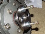
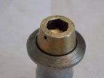
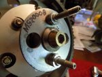
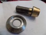
You have got me thinking now! I DID increase the length of that bolt because I didn't feel 4 threads was enough engagement. There is a chance, since I was trying to benefit from every single thread, that the bolt is bottoming in the hole and never achieving the clamp pressure,
That make sense even though I would hope I have more forethought than that! I will torque it all up and see how much force is needed to rotate the aft drive flange. If it seems low, I will cut 2 threads off the bolt length on the lathe.
I DO think however, I will go to 1/2"-20 for the bolt to get more squeeze.
Thanks again Dennis. I would have never thought to check that because I was CERTAIN I had checked and double-checked before choosing the new bolt length.
As you say, that makes more since than anything, if you had the stack-up (sandwich) correct.
I want to take this opportunity to use as a history lesson, and hope that it will help demonstrate some of what I was up against selling the Mini-500.
People just love to tinker and customize their stuff, especially if they are required to put it together themselves... let alone compounding the problem of making assembly mistakes or knowingly leaving a handful of parts off not knowing where they went, and still flying the aircraft incomplete and modified, even without inadequate dynamic balancing, and in most cases none at all, and then wonder why they had problems and shift the blame to the factory.
Yes, we at the factory were not perfect, nor did we design the world’s first and only perfect helicopter off the line without some growing pains, as many of you seemingly expected I should have been able to do, but this greatly compounded what we had to deal with to resolve any of our own design or manufacturing problems.
Every Mini-500 was assembled by someone other than our people at the factory, so every case of a customer calling for help was different. My people were like forensic investigators, trying their best to ask the right questions to drag the information out of the customer, all over the phone miles away, so we could help solve their problems. In almost every case, it would lead to some change the customer made, or something he did wrong, if we could drag the truth out of them at that time. But, the first response we received from him was "I did everything right and according to the assembly manual", which just made our jobs harder, because the customer was always looking for warranty to cover their problems. Hell, we all do that.
I would have never thought to ask Bryan if the changed the bold to make it longer. We would just assume he used the right parts in the right place according to the assembly manual. So weeks would have passed talking over the phone, with the customer being discouraged because we can’t figure out what the problem is, and him thinking we must be stupid or something. This happened all the time, until we would finally get our hands on the aircraft and find the undisclosed truth, in which case the customer would have said he didn’t disclose that because he didn’t think that made any difference….. and never with any apologies for not answering with the truth in the first place and causing us to spend so much time on his behalf trying to help. It was a very hard job.
The great thing about Europe is that they can fully assemble and test fly every vehicle, and then handed the customer something in a working condition that flew correctly and smooth. That was the big difference, not that they designed better aircraft, but they had control over the vehicle when and after it left the factory.
This is why we had such a strict contract that discouraged people from making changes. Not because I was some power-hungry Nazi on a power-trip. I just needed a way to try and limit this type of activity so that we could not only have a better chance of helping our customers, but so that we would have a fleet all operating under the same conditions so that if problems occurred, we could better determine if it was a design mistake or just an assembly mistake.


") . I just hate this NEW forum format and don`t come here as often.
. I just hate this NEW forum format and don`t come here as often.