Hey Chuck, I have lost a few emails from you with some info

skyguynca

Gold Member
Joined
Sep 23, 2004
Messages
1,413
Location
Acampo, CA
Aircraft
depends on what I have sold recently
Total Flight Time
5000+
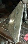
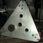
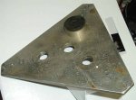
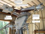
Some time ago we had discussed the different rotors you made for you gyro and helicopter. I remember you talking about using 3 biscuit engine mounts to attach the head to the hub, The main rotor mast was 4130 1 3/4 od x .1875 wall tubing. I remember the head was made from 4 plates 6061T6 .093 bonded together. I found the drawings you sent me on the setup. I also remember you telling me that it needed to be flown and tested with strain gauges. You had never gotten around to it and since you were not planning on flying it often, and you never flew higher than you'd be ok with falling, you just never got around to doing the strain gauges.

I think I some how lost some of the stuff but have some questions if you don't mind.

So why not use a solid plate of .375 6061T6? You had said the individual .093 plates were bonded together structurally, was there a advantage to bonding the plates together over a solid plate?

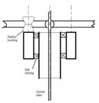
I found some of the pictures and description about the feathering axis setup, but I can not find the drawing for the feathering shaft, do you still have it?

I can not find the bearing part number for the main rotor shaft bearings, lost it with the feathering axis bearing number and feather housing and shaft drawings.

I have attached some of the pictures and drawings you had sent me, to help refresh your memory about the discussion.

I tried a old email I had for you but it gets returned. My current email is [email protected], I had two different emails previous to this one some time ago.

David M.
San Jose, ca
 

Attachments

  • hub 1.jpg
    hub 1.jpg
    16.7 KB · Views: 2
  • hub 2.jpg
    hub 2.jpg
    17.2 KB · Views: 2
  • hub.JPG
    hub.JPG
    39.6 KB · Views: 2
  • Floating head.jpg
    Floating head.jpg
    13.2 KB · Views: 2
  • rotorheadpowered.jpg
    rotorheadpowered.jpg
    181.5 KB · Views: 3
A laminated plate is a bit like plywood as opposed to a uniform plank, -cracks don’t propagate. Aluminum has a grain structure that needs to be scrambled.

The cyclic control of the 3-blade rotor hub with plate was about the same as the 3-blade rotor with fiberglass hub; the fiberglass hub used a spider arrangement whereas the laminated hub has the control stem poking straight up with the 3 cyclic pitch links connected to the top of it.

The principle behind floating hub rotors is that so long as the hub can be aligned with the rotor tip plane axis, flap and drag hinges aren’t required. Do a Google search for Doman helicopters.

I don’t remember bearing numbers either; the first 3-blade hingeless rotor was flown in the 1970s.
 
Chuck: I found this: "Test pilots reported the absence of high vibration and ease of control. Due to it's stability, the craft could be flown without having a death grip on both yoke and cyclic sticks." Do you have any test data that shows negatives about this rotor head design? So far it sounds like it might even dampen the 3/rev frequency? I'm curious why the design wasn't pursued by other helicopter mfrs.
 
My only intent with this floating hub rotor was to explore hingeless rotors and and to debunk Martin Hollmann’s misconceptions about Coriolis force.

During the initial test flight at a SRC flyin, Martin had gathered up an audience and was explaining to them how it was going to fling itself asunder because there were no drag hinges to relieve Coriolis force just as I came motoring sedately past. As related to me afterwards, someone in the audience said; “turn around Martin and you can see the thing flinging itself asunder.”

Martin was never able to grasp the concept of Coriolis force being an imaginary force that permitted a frame of reference change.
 
Chuck, I renew my call for you to write a technical book or at least your memoirs. :hail::hail::hail:
Brian
 
I really struggle reading books, but I'd certainly put the effort into reading a book from C.Beaty.
 
Smack;n1121808 said:
Chuck, I renew my call for you to write a technical book or at least your memoirs. :hail::hail::hail:
Brian

I second the motion... And suggest publishing his many contributions to rotating wing science in one big tome, 'The Collected Papers of Chuck Beaty'. I'm sure it would sell very well...
 
C. Beaty;n1121802 said:
My only intent with this floating hub rotor was to explore hingeless rotors and and to debunk Martin Hollmann’s misconceptions about Coriolis force.

During the initial test flight at a SRC flyin, Martin had gathered up an audience and was explaining to them how it was going to fling itself asunder because there were no drag hinges to relieve Coriolis force just as I came motoring sedately past. As related to me afterwards, someone in the audience said; “turn around Martin and you can see the thing flinging itself asunder.”

Martin was never able to grasp the concept of Coriolis force being an imaginary force that permitted a frame of reference change.

Chuck,

Is Coriolis a actual force, or is it a perceived effect? I've seen it written both ways.
If I understand correctly, it's an just an effect?
 
gyromike;n1121825 said:
Chuck,

Is Coriolis a actual force, or is it a perceived effect? I've seen it written both ways.
If I understand correctly, it's an just an effect?

I'm also interested in reading an explanation by CB. I understand that Coriolis is frame-of-reference-dependent, but can't see how it may be 'transformed away' in the floating hub rotor. After all, within that rotating frame of reference, the Coriolis force is very real...
 
When an artillery shell is fired along a N-S path, it travels in a straight line when viewed from space, just as Newton said it must.

When viewed from the Earth’s surface, it appears to follow a curved path as a result of the Earth’s rotation.

That’s where French scientist Coriolis comes into the picture. Newton said something like; “an object in motion travels along a straight line unless acted upon by an external force,” so Coriolis came up with an imaginary external force so that calculations based on the surface view could be handled without violating Newton.

Rotor blades, viewed from the shaft axis appear to flap and if they flap, they must also lead-lag to maintain angular momentum. But rotor blades in reality don’t rotate about the shaft axis; lead-lag-flap hinges are in effect a universal joint that permits a blade to rotate about its own axis, no different from twirling a rock on a string.

Does the rock flap? Does it lead-lag? We might imagine it to do so if the twirler’s wrist or forearm was taken as the rock’s axis of rotation.

Viewed from a rotor’s true axis of rotation, the tip plane axis, the blades don’t flap, don’t lead-lag and only undergo a cyclic pitch variation. Therefore, if the rotor hub is connected to the rest of the machine by a universal joint so that it is automatically aligned with the tip plane axis, there is no compelling need for flap and lead-lag hinges.

Blame it on Cierva.
 
Last edited:
C. Beaty;n1121829 said:
When an artillery shell is fired along a N-S path, it travels in a straight line when viewed from space, just as Newton said it must.

When viewed from the Earth’s surface, it appears to follow a curved path as a result of the Earth’s rotation.

That’s where French scientist Coriolis comes into the picture. Newton said something like; “an object in motion travels along a straight line unless acted upon by an external force,” so Coriolis came up with an imaginary external force so that calculations based on the surface view could be handled without violating Newton.

Rotor blades, viewed from the shaft axis appear to flap and if they flap, they must also lead-lag to maintain angular momentum. But rotor blades in reality don’t rotate about the shaft axis; lead-lag hinges are in effect a universal joint that permits a blade to rotate about its own axis, no different from twirling a rock on a string.

Does the rock flap? Does it lead-lag? We might imagine it to do so if the twirler’s wrist or forearm was taken as the rock’s axis of rotation.

Viewed from a rotor’s true axis of rotation, the tip plane axis, the blades don’t flap, don’t lead-lag and only undergo a cyclic pitch variation. Therefore, if the rotor hub is connected to the rest of the machine by a universal joint so that it is automatically aligned with the tip plane axis, there is no compelling need for flap and lead-lag hinges.

Blame it on Cierva.


What a great explanation Chuck!!! U-ROCK!
 
Jean Claude DEBREYER posted the best illustration of non-flapping I've ever seen; a plank spinning on the end of a rope but I’ve lost the link to his video. Perhaps he could be persuaded to post it again.
 
In physics, I'm just an amateur, but I believe, in my amateurish way, that –when talking about the necessity of a lead-lag hinge– the 'Coriolis approach' is as correct as the 'angular momentum preservation approach'. The first is a purely kinematic approach, where we invoke a Coriolis acceleration that, for any mass involved, results in a force, the 'Coriolis force'. The second is a dynamical, more direct approach. But they are just two different ways to see the problem, both of them fundamentally correct...
 
Chuck:

I remember you writing about this back in the late 80's when I first got interested in gyro's. There was a PRA mag article or some such. I was intrigued back then and I am intrigued by it now. If I recall correctly, the whole object seemed to be about making the center of a rotor hub itself a u-joint, mounted on top of a rotational bearing. The rotor gets all the freedom about the center of the rotor, limited by the freedom of the spherical bearing (or u-joint) in the lateral and longitudinal directions and mix thereof. The flap teeter blocks and hinge are no longer needed in that case in your experience and theory. While Sikorsky had an articulated lead/lag flap droop arrangement for the CH-3 and CH-53 blades, the actual hub had a spherical bearing that was attached to the rotor drive mast for the longitudinal and lateral movement about the mast axis.

To control such a u-joint arrangement would require a swashplate. Yours had a pitch change arrangement. The three blade gyro had both cyclic and collective.

Was the collective really necessary?
Was the cyclic control of pitch necessary?
Could one just apply force to the disk to change the direction of lift as we do now for semi-rigid rotors?

I may be just restating what has already been discussed long before, but the subject came up again. OR maybe I am misunderstanding your concept.

Thanks in advance

Curtis Scholl
 
It is impossible to tilt a rotor against its own inertia. A rotor is tilted by applying some form of cyclic pitch to the blades and letting them fly to a new position.

In the Cierva scheme, tilting the hub can only rotate the individual blades about their feathering axes because flap-drag hinges are in effect universal joints.

Same with a Bensen teetering rotor system; tilting the rotor head can only apply cyclic pitch to the blades.

Without teetering or flap-drag hinges, feathering cyclic pitch is essential.
 
Chuck:

Thanks for the explanation. Very well, if I get that far I will copy the Huey arrangement of swashplate and leading 90 degree cyclic input. Only because I am familiar with it and it would adapt to three and four blade rotors. For now I am working on a Hornet with a Bensen/Brock style rotor head.

Thanks again

Curtis Scholl
 
Top