SH PSRU Pulley removal

dunc

Active Member
Joined
Aug 1, 2016
Messages
255
Location
Crawford, CO
Aircraft
AR-1C 915is, RAF/SH/SC
Total Flight Time
5000
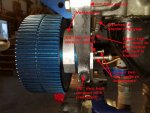
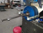
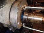
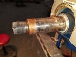
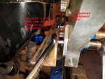
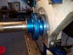
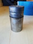
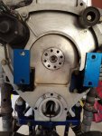
I have a newly purchased RAF with SH conversion. I am attempting to remove the PSRU pulleys inasmuch as the bearings have not been inspected/replaced per logbook, plus the prop shows significant play. I have not found any documentation on this (help!), and this is my first "return to airworthiness" step. First, correct me in the assumption that I will need a straight jaw gear pulley puller to remove the pulley from the jack-shaft. It will need at least a 8 inch spread, and a 5 inch reach. On order. I do not have a bench press.

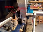
Loosening the four 3/8 inch "horseshoe" bolts, and removing the 1/2 inch thru bolt tension lock allows the 3/4 inch hex head tension adjust to be turned, but with difficulty, and only with a cheater bar. Assuming I can remove the prop pulley, I think removal of the jack-shaft and eccentric assembly will be difficult. Can anybody suggest the best way to remove this? I will want to remove any corrosion found there. Is use of anti-size suggested? Type? Tension adjustment guidelines documented?

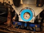
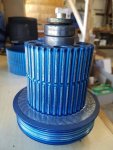
I also have a long 5/16 hex socket wrench (set) on order for the upper crankshaft pulley. It appears that a simple strap wrench can be used to hold the crank while removing the eight hex head bolts. Is there any documentation or discussions about this pulley removal and inspection?

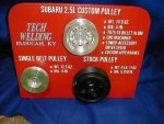
I read Mike Burton's article "SH PSRU upgrades" about steel sleeving these pulleys with great interest. Anybody else have done this or offer similar ideas of improving this high stress, and crucial area?

Thanks in advance!
 

Attachments

  • photo129073.jpg
    photo129073.jpg
    114.7 KB · Views: 7
Merry Christmas Dunc & congrats on your purchase & welcome to the gyro world !

I see that your parts are blue anodized, which would lead me to believe that those parts are RAF used to do the SH conversion ?

We just went through Andy's entire PSRU (new) to make sure it was all installed properly. (all SH parts). We could not adjust the tension with the "horseshoe" tightened. So obviously that also helps keep the belt tension in addition to the pinch bolt.

I never saw the entire thing disassembled...so I am curious also. The one thing we could not find info on was the torque spec for the large center shaft nut. So we snugged it logically & installed cotter pin.

Did you remove that nut ? Duh. OK. I would think that the pulley should come off pretty easily. I do not know how the center shaft is attached. What do you think holds it to the back plate ?

I have heard about putting steel sleeves in the RAF aluminum pulley, where can I read Mikes articles on that ?

I could see the steel adjuster wanting to gall in the aluminum back plate.....I would probably coat that with Never seize.

Could you post some photos of the entire machine ?

We could not get a wrench or socket on the front crankshaft bolt to hold the motor & I did not have a strap wrench there to hold the small pulley, so I devised a way to jam the pulley while we loctited & torqued those bolts. I think the CS output shaft is keyed. Do you feel that the CS pulley needs to come off also ?

I know we have the tension specs.......It was like 1/8" or 3/8" belt deflection, but don't quote me on that. I can find it if you need.....I was not overly concerned because the belt is brand new & the tension will be rechecked after initial run in.

So good luck & keep us posted.....maybe someone smarter will chime in here.

BTW....is that a 2.2 on you machine ? Carb or FI ?

Did Santa come to your house ? HO HO HO !
 
Rob, I thought you were logged on......maybe later.. Have a great Christmas !
 
Santa's tool delivery was postponed until tomorrow. I can't continue until I get the prop pulley off. I dunno if these are RAF or SH pulleys. Log books are cr@p. I am just a gyro newbie, but a&p for 20 years. It has a Soob 2.5 L FI engine and I will be checking timing belt among other things. I have SC rotors and head on order, but have a lot to do before it is airworthy in my opinion. Will be replacing all heim joints and the stick push rod for sure.
 
I sure can't wait to see why a spinning part like that is so hard to get off. Good luck & keep us posted.

Do you think you will be sleeving that pulley ?
 

Attachments

  • IM000524.JPG
    IM000524.JPG
    93.3 KB · Views: 4
  • 7353381_orig.jpg
    7353381_orig.jpg
    33.7 KB · Views: 5
C'mon guys.....who's gonna help us get this pulley off of here ?

Rob , do you have the conversion instructions ?

PS.....got your email, will reply.
 
I have four horseshoe bolts, so I "think" this is a SH PSRU setup. It makes sense that the bolts must be loose in order to set the belt tension. However my upper two bolt heads hit the flywheel starter ring gear when unscrewed just about 1/2 inch , and therefore can not be removed unless the lower pulley is first removed. The horseshoe hits the pulley if pulled aftward (is this a word?) when attempting to provide more space for further unthreading. I am just wondering if this is a 2.5 L vs. 2.2 L engine flywheel difference. i.e. Can you remove your upper horseshoe bolts without hitting the flywheel? Puller via Santa FedEx delivery scheduled for today.
 
Rob, I doubt that there would be any more bolt clearance on the 2.2.

So you feel that the inside bearing surface is stuck(rusted) onto the main shaft ?

You also think that with a puller you will be able to pop her off ?

Andy's SH pulleys are not anodized & I am not even sure that they are aluminum. They are SH pulleys.

I do not know if the RAF-SH conversion kit reused the RAF pulleys or not.

I also do not know how the pulley spindle shaft ,with eccentric adjuster is fastened to the mounting plate. I have to take things apart to understand them. If you get yours apart, please post some pics with the descriptions & arrows. I wished I knew how to do them !

Did fedex get there yet ?
 
No Title

Since you have a 2.2 L, did you ever back out the upper horseshoe bolts enough to see if they hit the flywheel ring gear? Just curious. It seems like I would need to remove the engine, or at least lift the rear end a bit, in order to replace these two bolts. It is a shame, as it is only about 1/8 inch interference.

The ATD Tools Model 3047 Straight jaw puller (just $44 at Amazon Prime) arrived, and worked very well. This is more than adequate for the task, and might be a good purchase "just in case" your own bearings get seized to the prop jack-shaft. Both bearings were corroded to my shaft. Note the inner bearing stuck more to the shaft, than to the pulley, requiring its separate extraction after pulley removed. I have cleaned the shaft and now the old bearings slide on easily. Maybe too easily? Will be ordering replacements today. Although the bearing to pulley looks "tight", I will be making final determination about adding steel inserts. Will use a local machine shop.

Here is Mike Burton's post on the subject:
https://www.rotaryforum.com/forum/k...sparrowhawk-gyroplanes/24068-sh-psru-upgrades

I still want to remove/inspect the jack-shaft eccentric housing. I will likely devise my own "jack-shaft puller" as it remains quite stuck, requiring an 18" cheater bar to turn the tension adjustment, even in this disassembled state.

Upper crankshaft pulley will be removed today if the hex socket set arrives.

Descriptions, but no arrows!
 

Attachments

  • photo129081.jpg
    photo129081.jpg
    52.8 KB · Views: 3
  • photo129082.jpg
    photo129082.jpg
    40.9 KB · Views: 3
  • photo129083.jpg
    photo129083.jpg
    43.6 KB · Views: 3
  • photo129084.jpg
    photo129084.jpg
    35.5 KB · Views: 3
Rob, glad you finally were able to remove the large pulley. The jackshaft was indeed corroded as suspected.
The crankshaft may be in similar condition, and you should definitely replace the small pulley bearings while you're in the guts of it all.


Although the bearing to pulley looks "tight", I will be making final determination about adding steel inserts. Will use a local machine shop.
The prop had considerable play during my pre-buy inspection for you, so something (pulley, bearings, and/or shaft) is quite worn. (I suspected the pulley.)
If you're lucky, it's merely the bearings (which the previous owners should have replaced long ago, per the maintenance schedule).
The new bearings should not, as you know, too easily press in the pulley or on the shaft.


I will likely devise my own "jack-shaft puller" as it remains quite stuck, requiring an 18" cheater bar to turn the tension adjustment, even in this disassembled state.
That's likely because the cam is corroded within the rear mount.
As I emailed you, some Kroil may help break it free, but it's a wise idea to disassemble those parts for your own inspection/experience.
Do very carefully inspect the rear mount for cracks and relieve all potential stress risers (such as the sharp bolt hole edges).

_________

I have SC rotors and head on order, but have a lot to do before it is airworthy in my opinion. Will be replacing all heim joints and the stick push rod for sure.
You will enjoy great relief not having to worry about a 650 hour OEM RAF rotorhead and the older crack-prone hubbar.
I applaud your sensible decision to "damn the cost!" and go with the Sport Copter rotor system. You'll love it.
Please do not be tempted to sell your old RAF hubbar or blades, as they are timed out by 150 hours.
(Perhaps assemble and hang the rotor span as a cool piece of hangar art?)

The SC air-trim will require particular focus of training, to learn to "feel" the best rotorhead orientation at beginning of take-off roll and reflexively adjust along the roll.
It takes a bit of practice, especially when adding/subtracting a passenger, and dealing with x-wind takeoffs.
Choose a CFI with experience in the SC air-trim system.

Regards, Kolibri
 
Last edited:
Kolibri;n1128381 said:
Rob, glad you finally were able to remove the large pulley. The jackshaft was indeed corroded as suspected.
The crankshaft may be in similar condition, and you should definitely replace the small pulley bearings while you're in the guts of it all.

Have taken both pulleys to local machine shop and will be adding the steel inserts for both prop bearings. My old prop bearings have gone from "solidly corroded on" to "easy to slip over jack-shaft" with just some solvent cleaning. This seems too loose to me, and the old bearings measure true on the inner races. Machine shop wants to review the jack-shaft once I get it out. The inner bushing on the crankshaft pulley sleeve is also solidly frozen, but they will press it out tomorrow.

Kolibri;n1128381 said:
That's likely because the cam is corroded within the rear mount.

Applied more mouse milk to eccentric cam today and will let soak another day. I will likely be home brewing some sort of press/extraction tool tomorrow.

Kolibri;n1128381 said:
(Perhaps assemble old RAF rotor and hang as a cool piece of hangar art?)

Maybe with a geared electric motor as a "big ass fan"?

Kolibri;n1128381 said:
The SC air-trim will require particular focus of training, to learn to "feel" the best rotorhead orientation at beginning of take-off roll and reflexively adjust along the roll. It takes a bit of practice, especially when adding/subtracting a passenger, and dealing with x-wind takeoffs. Choose a CFI with experience in the SC air-trim system.

That's for sure! I have spoken to others about pneumatic vs. electric trim systems and leaning again towards pneumatic.
 
No Title

I am happy to help as I can, oh eutrophicated one (had to look that up!). I have spent a lot of time on other helpful forums for computer and aircraft information. It only helps us all, or at least the next guy!

As my eccentric assembly was very tight, I built a simple "eccentric extraction tool" by drilling two holes in a piece of angle iron. I used the removed horseshoe lower two holes to set the spacing, and 5/16" x 2 1/2" bolts thru the lower two holes. The 3/8" nut spacer gave extra room to use my 1/2" socket. Tightening each in turn worked well, right up to the last 1/2 inch or so as it bottomed out against the engine mount. The eccentric was still quite stuck, so I inserted a small socket between the new tool and the tension adjust bolt head for the last part. I hope the remaining pictures are sufficiently captioned.

Once removed, I found no unusual reason for the difficulty in turning or removing the eccentric - i.e. no corrosion or scuffing. The mounting hole is just very tight. My eccentric will require some force to reinsert. I have tried wedging the lower gap to open the eccentric mounting hole but it is resistant. This resistance seems reasonable due to its substantial surrounding structure. But unless the hole is widened, then belt tension adjustment will require a cheater bar on the adjustment bolt head.

Q1 - Should the hole be made wider for easier eccentric insertion and facilitate subsequent belt tension?

I originally planned on using 3/8" bolts for my custom extraction tool, but found that the hole through the engine mount part connected to the chassis is not exactly aligned with the hole on the rear engine/PSRU mounting plate (name?). This will be problematic during reassembly. I figure a "tapered bolt" or punch may work well enough for realignment. That's why I used 5/16" bolts.

Q2 - Any suggestions for realigning these lower two holes as I replace the lower two horseshoe bolts?
 

Attachments

  • photo129095.jpg
    photo129095.jpg
    142.3 KB · Views: 3
  • photo129096.jpg
    photo129096.jpg
    156.7 KB · Views: 3
  • photo129097.jpg
    photo129097.jpg
    99.8 KB · Views: 3
  • photo129098.jpg
    photo129098.jpg
    102.8 KB · Views: 3
  • photo129099.jpg
    photo129099.jpg
    61.1 KB · Views: 3
  • photo129100.jpg
    photo129100.jpg
    106.2 KB · Views: 3
Rob, at this point, why not remove the whole backing plate ? What is it.... a starter & 6 bolts to remove ?
This could make the restoration job easier & maybe use shorter HS bolts ?

Can anyone confirm......SH offered no anodizing ? All blue parts are RAF ?

BTW... where is your coolant temp sensor ?
 
Last edited:
Chris, Why? If it appears useful to remove, I have no problem. For your other question, this is the very first Soob engine I have seen, ever. Obviously I need to get a manual, but have not been successful in determining which one to get, exact model, etc. Most stores say "what year and model car is it" and I am clueless. But there a a couple "sending units" that appear over the right cylinders where the coolant line goes in. Just my guess for now, but will send pictures if needed. My plan is to finish all airworthiness items, learn to fly well, then get into the engine, change timing belts, add a turbo, maybe adjustable pitch prop, etc. Gotta see how much I like her first beforehand.
 
We're not sure if we are supposed to use the stock sub sensor through the ecm or like I did... a seperate one. Just trying to learn some stuff without going to the airport to look at Larry's RAF/SH conversion.

Did you see any of my threads ?

I am bored....had snow last night, & cold to go with it !

Here is a pic of my gyro wagon...77 Chevy....2 times to Bensen Days....2 times to Rotors over Carolina....twice to Mentone

Also picked up a gyro from AC in Texas & delivered it to Shasta mountain in California.
 

Attachments

  • IM000386.JPG
    IM000386.JPG
    87.1 KB · Views: 3
  • IM000429.JPG
    IM000429.JPG
    80.2 KB · Views: 3
  • IM000426.JPG
    IM000426.JPG
    78.1 KB · Views: 3
Last edited:
Rob, you be learn' and stuff! :yo: Kolibri
 
Alright...what's happening ?
 
Still waiting for any SH owner to reply about excessive tightness on the eccentric mounting hole, or suggestions for realigning the engine mounting bracket holes.
 
Mornin' Dunc.......I have been trying to follow your progress.....getting a little scattered...

please try to keep us updated......I love this stuff ! THANKS & Best of luck.
 
Top