Antenna placement question.

mvadney

gyroboy
Joined
Aug 8, 2004
Messages
65
Location
Arlington
Aircraft
Sportcopter Vortex
Total Flight Time
300
Hello all.
I am finally near the end of my build and I wanted to ask a question about antenna placement. I had initially installed the antenna on the nose, but Matt at MGL said that the antenna being so close to the IEFIS and SP6 compass will most likely cause some painful electrical signal issues. My question is, would mounting the bent version of the Red Tail antenna pointing down and under the keel mess with the performance of the antenna? I am thinking that I would mount it right in front of the angled rear boom/keel beam joint. I know from the past at the Mentone conventions that I would loose the air boss' radio on 18 being that a hill is present. I can live with that, but other than that would I be ok?
Thanks,
Mike
 
I don’t recall seeing a picture of your build Mike.

It is hard to offer advice without any idea about the structure or lay out.

I have seen antenna location make quite a difference in radio performance.

If it is similar to a Sport Copter I would ask Jim Vanek because he has probably tried many locations and would know the good and bad of each
 
Hey Vance.
It looks pretty much like Carl's raised Bensen
 
Hopefully Paul Plack will chime in here as he knows a lot about antennas.

I would be inclined to put in it the nose and manage whatever problems it causes with the IEFIS and compass.
 
Even the antenna mfrs will tell you that the bent antennas have a VSWR (ask your local ham) of a minimum of 3. This means your range of operation is reduced. Personally, I will never use a bent antenna.
 
Would you show us photos of your build, Mike?
Did you part ways w/ your Sport Copter w/ the HKS (?) engine?
 
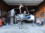
Here it is. The Red Tail Antenna is on the nose. Its about 2' away from the IEFIS and less than a foot to the compass. According to the MGL folks they say that this is just too close. I can always try it where it currently is situated, but I expect to move it.
 

Attachments

  • IMG_2010.JPG
    IMG_2010.JPG
    63.5 KB · Views: 15
Hey Kevin.
No, I still have the pokey Vortex. Very reliable though. This gyro will replace it once I get it inspected. It has the turbo version of the HKS engine and a 70 or 71" prop on it.
 
Nice pic of the Carbon Carlinator or the Carbon Fibernator, whichever it is!
 
I cut a 10" round disc out of aluminum as a ground plane. I mounted it in the center of the pod directly under what would be the front edge of the seat. If you drew a straight vertical line in your above photo; it would place the antenna about mid thigh.
It pointed straight down and the ground plane would protect you from any radiation (not as strong as a transponder antenna would be so no worries anyway). Only required a 3/8" hole in the pod and the disc was secured with a bit of silicone sealant in addition to the antenna fitting bolt. I ran a 50 ohm coax to the connection with a 90 deg. bnc connector on the antenna end for ease of cable fitting
(right along side the keel tube and secured it with a few (not pinching) zip ties. Never had an issue and the radio worked like a champ.
 
Last edited:
mvadney;n1131348 said:
...Matt at MGL said that the antenna being so close to the IEFIS and SP6 compass will most likely cause some painful electrical signal issues.

Mike, that is a really cool build!

Matt's concern is justified. The distance between the antenna and the pod might be manageable if you could keep RF currents from flowing on the outside of the coax shield, but the pod is actually higher than the base of the antenna, right in the strongest lobe of the signal. That location also makes it really tough to fashion a proper ground plane, which is critical to making that antenna work. It's designed to be used on a metal-skinned airplane, and needs something equivalent in a gyro. A keel-mounted antenna would be a much better choice, if only because you can use the keel as a component in the ground system, and have room to lay out ground radials in the needed directions.

My question is, would mounting the bent version of the Red Tail antenna pointing down and under the keel mess with the performance of the antenna? I am thinking that I would mount it right in front of the angled rear boom/keel beam joint.

Mike, that antenna has no provision for retuning to adapt to unusual installations, and proximity to frame members will require retuning to achieve the advertised SWR bandwidth, It will also result in some directions having uneven coverage in some directions. Mark's proposed location, centered under the pod, is probably best. Mount the antenna using a piece of thin 2" angle attached to the keel inside the pod. That connection between the ground side of the antenna and the keel should be enough ground to keep the transmitter happy and give reasonable performance, but will likely result in fore/aft directions having better coverage than side-to-side.

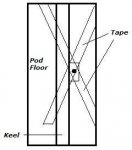
A way to improve the tuning and coverage further is to make a big "X" out of 2" adhesive-backed aluminum tape (see diagram), sold for use in HVAC systems. Get both strips as close as you can to 40" long, and stick it to the inside floor of the pod with the center of the "X" at the antenna mount. (If you apply the tape first, you can sandwich it between the aluminum angle and the tape, and put the mounting holes right through the tape.)

It's not always practical to get the tape strips 40" long, (the four legs of the "X" extending 20" from the antenna mount,) but if you can, the antenna will show a significantly lower SWR in the 118-122 MHz range, where most gyros do most of their transmitting. That low SWR will greatly reduce RF currents flowing on the outside of the coax shield, which minimizes problems with your transmitted signal interfering with proper operation of your avionics and instruments.

You can cover the aluminum tape strips with colored duct tape, paint or any other insulating material to hide it if you want.

The bent version of the Red Tail should have an SWR similar to the straight version. These antennas are fine, but pricey for what they are. You can make a functional aviation COM antenna out of CB antenna parts from a truck stop for a few dollars if you know how. But you need a good VHF SWR meter as minimum equipment to be successful.

Making radios work seems like a black art, but it's pretty straightforward if you plan ahead and have the right tools.


Keel Tape.JPG
 
Maybe I could make a "V" type dipole antenna instead and mount it on the mast?
Two 40" strips would be pretty difficult to layout on such a narrow pod I would think and the antenna wouldn't be centered in the pod. If I make my own antenna I would think that I should also buy a meter to tune it too.
Thanks Mark and Paul!
 
mvadney;n1131376 said:
Maybe I could make a "V" type dipole antenna instead and mount it on the mast?
Two 40" strips would be pretty difficult to layout on such a narrow pod I would think and the antenna wouldn't be centered in the pod. If I make my own antenna I would think that I should also buy a meter to tune it too.
Thanks Mark and Paul!

I would go with Pauls set up.
It will be the best system for your needs.
The ground plane is unique but functional and will aid in reception and reduction of standing waves.
Even if you don't make your own antenna you should still use a meter to trim the antenna.
The impedance match on an antenna is the most critical for best operation.
 
a few years ago, I purchased an antenna on Ebay. I communicated with the seller before I purchased. It was a 1/4 wave NMO mount with approx. 6' of coax and a BNC connector for my radio. I specifically requested him to trim the radiator/ antenna to be resonant at 122.8. I
If memory serves me, it was about $25 for product plus shipping.
 
Here is a post I made on a previous thread. Point is, it is fairly easy to build a "monopole" antenna and I choose to tune it for the frequency that I mostly use, which is 122.8 MHz. The point at which it is tuned will produce the best SWR results. and the farther off tuned frequency you get the greater the SWR will be. Below, you will find a formula to get you in the ballpark.

A quarter-wave antenna is theoretically 36 ohms since it's half of a dipole antenna which is 72 ohms. The dipole antenna needs no ground plane but can you imagine a 46" antenna sticking up somewhere on the outside of our gyro's.
On a dipole, the shield of the coax feeds one half of the antenna while the center wire of the coax feeds the other half. In a quarter-wave antenna installation, the coax's center wire feeds the insulated antenna element while the shield "feeds" the ground or is grounded to the metal structure. The metal material around the antenna becomes the other half of the antenna system. Even though this is not a di-pole in the purest sence, electrically it is still a di-pole, being that the aircraft structure becomes the ground plane.

The formula for figuring a half wavelength is: 492 / freq(in MHz) x 12 to give the length in inches. So to figure a quarter wavelength, the formula would be: 246 / freq(MHz) x 12. However, those figures are generally for frequencies below 30 MHz or so (shortwave bands). It's been found that as your frequency increases above 30 MHz, the ends of the antenna begin to affect the real world length and calculations need to be adjusted dowm about 5%. So we use a slightly different formula: 236/freq (MHz) for antenna lengths at our operating frequencies for real world applications.

Example:
find a quarter-wave antenna length for a 121 MHz operating frequency.
(236/121x12) 236 / 121 = 1.95' x 12" = 23.4" for the rod.
The ground plane radials should be 5% more or about 24.6". If they are longer, it's not a problem.


If, for example, you use 118.0 MHz for the lower end of your "operating range of channels" and 126 MHz for the upper end, you'll find that the center frequency will be 122 MHz. Therefore if you cut your antenna for 122 MHz it will be the most efficient at that frequency with a slight loss at 118 and 126. This loss will only be measurable with an SWR tester. The lengths for those two frequencies will be approximately 23.8" for 118 MHz and approximately 22.3" for 126 MHz. So we have a difference of 1.5" over that 8 MHz channel spread. This is why we say the length is nothing to get really concerned about. In our 121 MHz example, a half inch either way from the 23.4" calculation will work just fine. Of course, there comes a point where the SWR is a problem, I personally trimmed my radiator (antenna element) to be resonant at 122.8 combined with an attached ground plane in base of my pod. This gives me the best SWR of 1.1to 1; the farther off frequency you go the greater the SWR. But, at the extremes of our range, I still only see about 2 to 1. Please note, the higher the SWR the less efficient the transmitting system becomes and will cause internal damage to your radio.
The ground plane, or counterpoise as it's actually called, is at the base or feedpoint (where the coax is connected) to the antenna. Ideally, the ground plane would be a disc with a radius of 5% or more than the active (vertical) element or, in our example of 23", about 24-1/4". However, on our gyros, it is not practical. We can use 4 wires or rods in place of the disc with excellent results but again, depending on the aircraft/application, it may not be practical. In my particular application on my Dominator gyro. I utilize a piece of metal sheeting and basically lined the bottom of the pod, passing across between the keel and pod.
 
Now that's something to chew on. Thanks.
Now I have another twist. My fuel injection CPU sits on the floor, under the seat. Will the antenna and CPU so close cause problems? Should I now consider the mast as the mounting point?
Thank you everyone for helping out.
Mike
 
I went back and found the seller on Ebay. It was " antenna2-waydirect "
he has a NMO mount with BNC connector listed for $16.99 and an antenna's for about $12.00. If you send him your requirements, he will cut the coax to the length you want and trim the antenna to a length you want. He was real easy to work with. So, it looks like about $30 and it will show up in a few days in your mailbox.
 
Which one are you thinking Dave? I don't know squat about antennas.
 
Mike,

It is not impossible, but complicated, to get a vertical antenna of any type to work when mounted to a vertical mast. (And it needs to be vertical for aircraft COM work.) You'd need to model the antenna in software which could also model the structure to which it's mounted. The software's not terribly expensive, but an accurate virtual build of the gyro's frame would be very time-consuming. (Guess how I know!)

If you use a ground plane antenna extending down from the pod, you can make it work near your ECU, but it will have to be tuned precisely, or there will be signal radiated from the coax. That may rule out the Red Tail, because there's no way to tune it. I'd suggest placing the center of the antenna mount about midway between the ECU and the nose gear fork.

Cheap antennas can work great, but if you're putting it near the ECU, quality coax and optimized ground radials become critical. The radials not only allow correct tuning, but they choke RF current which could otherwise flow on the outside of the coax shield, increasing the odds of interference with other onboard electronics. I'd be a little worried about that $17 NMO mount. Cheap coax often has a braided shield with big gaps between the copper strands, which allows more leakage from the cable. If you're ordering one online, find out what spec, if any, the coax meets. You want 50-ohm coax with at least 95% shielding. If the seller lists the cable as RG-58, it may be cheap CB coax which will have poor shielding, unsuitable loss and leakage at aircraft frequencies. Preferred types are RG8M or RG8X. Some types of RG58 used in the early days of ethernet may have good shielding, but it's getting hard to find. (I recently saw some advertised with 48% shield coverage.)

A half-wave dipole loses some of its effectiveness if the two halves are in environments which are not symmetrical. I made a dipole and mounted it vertically along the door frame of the Sport Copter's pod. It was a big improvement, but it was detuned significantly as I moved my leg closer to the lower half of it while seated.

The right tool for tuning work is an antenna analyzer. Many ham radio clubs have an MFJ Model 259 for loan to members, or members who have one, and it is a great tool for this job. Many of these guys would love to bring their analyzer out to help, just to see your aircraft.
 
Last edited:
Top