Weber 750 & Megasquirt ECU

Hi Mark

Negative on the business address, will pm address.

Tony
 
Hi David,
Glad you got to see the Weber out in the shop.
I thought I would have the Megasquirt conversion finished by July the 4th week end. My Stimulator which is used for testing had a problem with the microchip that drives it.
It only cost $6 dollars for a new chip with updated firmware and $3 dollars shipping from Canada. If your remember there was a mail strike or something up north and I received my chip about 20 days after I ordered it.
So that put me almost to Aug before I could test the ECU on the bench.
Mean while, I made another change in the PCB by removing the on-board 3Bar Map Sensor and installed an on-board 4 bar Dual Map Sensor, (Map Daddy 4) this is more than enough sensor for the turbo but it was a much cleaner install, rather than running wires to a second Map Sensor on the motor in order to get real time Barometric Correction.
This little feature will be like having Altitude Compensating Carburetors

I will try to take some pictures tomorrow and post the changes. It was a very inexpensive modification to the Megasquirt 2 to upgrade to Megasquirt 2 Extra.

Now , I will have full Sequential port injection, Sequential Coil on Plugs and the stepper motor driver circuit. Which probably is not a big deal, but I want keep as much the same as I can.

I also bought a Pulse Driver for the Turbo Waste Gate solenoid. I will have to research it more, before I add it to the Megasquirt.

I will have to look it up, but I think all the improvements was about $60 dollars.
 
I have a hydrospace and was converting to microsquirt, but ran into a road block where the crank trigger would not come across properly. The signal was too weak. (as verified by my o-scope) are you running the stock crank trigger or other?
 
Last edited:
I am running the stock trigger. But I am running the Megasquirt, Tony is running the Microsquirt. , I don't know what setup he is using. It seems that has come up before, on someones hall sensor. I don't remember how they corrected it. Seems like they used the hall sensor out of a GM product, I cant remember for sure.
Did you give up on the Microsquirt? How did you get around the dual trigger or did you just use the crank trigger wheel and let the software make the adjustments?
If you are still looking at another ECU, I have been talking with another company that will offer a plug and play for the Weber at less than the Walbro.
Must be nice to own an O -scope.
 
The microsquirt does have two trigger inputs. I have the crank sensor (Variable reluctance) and the cam, a hall effect. The hall effect signal is an amplified output, digital signal. The crank is simply a coil that outputs an AC waveform. Unfortunately I don't get any crank pulses from the sensor as verified by tunerstudio. RPM = 0. I need to get a better sensor, move it closer to the trigger wheel, or build a signal conditioner that can handle the weak trigger signal. My preference would be to fix the pickup but it is buried in my engine and is a pain to work on in the jetski. One of these days I'll get around to making it work.:usa2:
 
Hi Mac,
Hope you get your Microsquirt going on the Weber. With the Megasquirt, I made a few small modifications to the Hall Circuit. If I remember correctly, a 330 ohm resistor was used for a 5 volt supply voltage and 1K ohm resistor for the 12 volt supply. I am hoping that since I put a resistor in for 12v supply for the Hall sensor, I will get sufficient signal for the sync.
I tested my board on the Jim Stim and it was working properly.

I am running the primary tach as the VR wave off the crank and 2nd Tach or trigger as digital off the Hall or the Cam sync.

After a while this stuff all sounds like spaghetti to me.

Mark.
 
Well,
I don't mind telling you that cutting this much off of the Bosch ECU and Polaris harness had me thinking, I should have worked on by passing all of the Snowmobile Safty stuff.

What you see laying on the shop floor is how much I removed.

I bought a new computer, loaded TunerStudieo on the Computer, attached it to the completed Megasquirte Extra ECU, Down load the most current Firmware, Fipped the power switch on the Stimulator and Bamb, I get this ugly message that my computer and ECU are not taking to each other. So it is best to go the the Megasquirt Extra Forum and get the Firmware that is listed there. After loading that release, I got an active program.
 

Attachments

  • 001.jpg
    001.jpg
    139.7 KB · Views: 0
  • 014.jpg
    014.jpg
    134.5 KB · Views: 0
With that resolved , I went on to wire in the Megasquirt to the Weber Pigtails, Most of them anyway. Another issue I ran into was the Cable , I purchased from DIY did not have the same wiring diagram as the schematic, I was using. So it was off to Radio Shack for some computer parts to rob the pins out of the fixtures and soldier them into the Megasquirt wiring harness. This gave me the extra wires I need to run the Hall sensor (second trigger) to the Spare#4 outlet. This will be Pin 6 on the DB37 connect. I also ran a wire to the Spare #1 position which is Pin #3 and that gave me enough of wires for the most basic inputs and outputs for the Weber engine.

The next obstacle to over come, was I had power with switch on, but it would end shortly after that. So I went to town and bought a new switch that was hot on the start side as well as the on side. The switch I had would drop the main hot when it was moved from "On" to "Start".

Bad switch,
Megasquirt without the case
added three wires here
 

Attachments

  • 031.jpg
    031.jpg
    135.2 KB · Views: 0
  • 027.jpg
    027.jpg
    134.1 KB · Views: 0
  • 028.jpg
    028.jpg
    136 KB · Views: 0
  • 029.jpg
    029.jpg
    136.4 KB · Views: 0
Last edited:
With the various issues I ran into, I decided NOT to Wrap the wiring until I have started the engine. I do not want to unwrap all of this to find a wiring fault.
 

Attachments

  • Weber pigtails.jpg
    Weber pigtails.jpg
    134.7 KB · Views: 0
  • 024.jpg
    024.jpg
    136.5 KB · Views: 0
  • 025.jpg
    025.jpg
    134.5 KB · Views: 0
  • 022.jpg
    022.jpg
    137.4 KB · Views: 0
Last edited:
With the Megasquirt wired into the Weber, It was time to make some preliminary checks with the Software (Tuner Studio)
 

Attachments

  • 026.jpg
    026.jpg
    135.5 KB · Views: 0
  • 030.jpg
    030.jpg
    135 KB · Views: 0
  • 001.jpg
    001.jpg
    132.2 KB · Views: 0
In the last picture above, There are a few problems showing up.
The ECU is On because the blue line along the bottom shows it it powered up. It it was not there would be a message across the screen, Working OFF LINE. or NOT CONNECTED.
Notice in the Middle of each gage there is a number that gives specific details for that gage.

Starting top left, is RPM which is correct because the switch is on, engine is not started.

Next is Throttle Position Sensor, which shows 100% on the gage with throttle closed and
-21%, so we know this is incorrect. Because Accel enrichment and engine load is also determined from this value, it needs correcting. More on that in a minute.

Battery voltage is a wee bit high, because I have a battery charger on the battery at 2 amps 12v.

Bottom is Coolant Temp. this is about 20 degrees too high, so the CLT will need calibrating as well.

Ambient Air Temp is satisfactory at about 73 degrees.

From the tools menu, I selected to calibrate the Throttle Position Sensor TPS and the dialog box drops down.
 
By clicking on the closed throttle position we can get our 0 scale voltage.

Then open up the throttle to wide open and click on full throttle voltage
Don't be alarmed if the gage goes Red, the engine is not running, When the gage was reading wide open to begin with, it will over shoot the perimeters when you really do open it up.
It will return to normal when you click on accept and make the new value the maximum value.
and your gage will now read 0 Throttle as it should.

I apologize for the poor quality of pictures , My Iphone is hard to hold and push the screen button at the same time.
 

Attachments

  • 002.jpg
    002.jpg
    137.2 KB · Views: 0
  • 003.jpg
    003.jpg
    135.2 KB · Views: 0
  • 004.jpg
    004.jpg
    132.2 KB · Views: 0
I will have to get 3 resistors values for the CLT. I don't have the weber book with me so, I will leave it for now. I cannot run the engine as I do not have a radiator at this time. I can see if it will start.
The first thing to do, if you are going to run it , is to establish a know timing mark of 10 degrees BTDC. This will allow you to verify that the trigger offset angle is correct in your programming. I think I used 114 degrees for this tune.

I Removed the fuel line positive wire, so the engine could not start and spin it over to verify the gages were working and to see if they are approximately correct. The Barometric press is just over 100. I have not run the vacuum to the intake at this time.

I will post a clip on you tube so you can see the gages as I crank the motor.

016.MOV - YouTube

An now the Weber starts on MEGASQUIRT

017.MOV - YouTube
 
Last edited:
Mark, I don't think I ever found the factory timing marks to be correct. I would use a degree wheel to find TDC and set the advance you need. I made a device to find TDC on each cylinder on a Magni M16 to make it easy to check the compression. The spark plug thread is 16X1.5MM on the Rotax 914 ULS. You would thread in a bolt just far enough that the piston hits the bolt slightly befor TDC. You mark the degree wheel at that point. You then turn the engine backwards until the piston touches again. You mark this point on the degree wheel. Half way between the two marks is TDC. If the factory marks are correct thats all. If it isn't you can log the difference between the factory and true TDC. You must make sure that the output clutch doesn't slip and allow for the reduction ratio in finding points in engine rotation. Attached is a pic of the degree wheel I made. Hope this helps, John K
 

Attachments

  • Degree wheel.jpg
    Degree wheel.jpg
    123.9 KB · Views: 0
Way to go, Mark!

Looks like your making some good progress on getting this engine figured out. What gyro are you going to mount this on?
 
LOOKING GOOD MARK

Hopefully will get out to the hangar today with my neighboor (the computer whiz ) and do an initial set up on the ECU. Can not start it as I don't have any oil in it or water or fuel set up yet but can verify the guage settings on the screen and maybe set the TPS and AIT .

Tony
 
John,
Thanks for the picture and information. I would like to see a thread on your degree wheel. That is very cool looking and I bet it is quick to find TDC as well. If you make another one or have pictures of your project, please post.

Gary,
Thank you, I need all the encouragement, I can get.
If I put it on a single place, it will be a Bensen with round tubing and curved keel. it will have a lot of the Wallis Gyro influence and the MTO3 .
If I put it on a two place it would be a stretched KB4, or a stretched Round tube Bensen.

Tony,
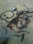
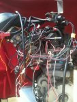
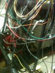
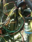
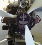
For this test, I ran the oil discharge back into the inlet. It just circulated the oil that was in the sump. I disconnected the reservoir for now while wiring. No Radiator so I did not run it, only made sure the wiring was sufficient to start the engine, before wrapping it in the plastic tubing.
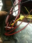
It is interesting, that prior to testing, I had the spark plugs out to check the spark. with out the coils fastened to anything but the plugs and the wiring harness, I got, good hot spark results, so the extra ground may not be needed. it Can't hurt to have them, I was just surprised as the good spark.
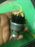
I don't know if you are programing sequential or Wasted Spark. In Sequential the Hall Sensor will be firing the plug on the PTO end, not the Mag end. The VR wheel will fire the Mag plug.
In Wasted spark, it probably does not matter as both plugs will fire each time the piston is TDC.
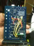
The Hall Sensor worked great even with a very weak battery.

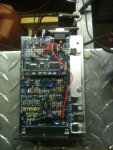
I must say that the engine really started easy, when you consider how much I changed and took off of it. I was one happy camper . My son said,. He remembers the Megasquirt all over the dinning room table. He stayed all day at my house and we put another MAC motor on my first gyro. We got it started, so this has been one of the best weekends a fellow can have.
 
I have not posted on the Weber/Megasquirt in a while. Mainly because I have not worked on it since Oct when I started it up.
I received this advertisement from DIY. It is for a Blue tooth adapter that will allow you to log your engine runs on an Android Mobile Phone and down load to a computer for Data Logging. With this device a person could record his engine runs from the phone rather than a laptop. This maybe a new way to record the engine in flight without a laptop. Just a thought.
What do you computer savvy guys think??

http://www.tunerstudio.com/index.php/shadowloggerms
 
Top