Rotor Airfoils
“As an inviscid and incompressible fluid flows, the total head remains unchanged,” so said Bernoulli in adapting the conservation of energy law to fluid flow. That means, in plain English, that without friction, energy of a fluid stream is conserved. But poor Bernoulli gets mangled by the aviators.
The end purpose of all airfoils is to change the direction, or more explicitly, the momentum of a moving airmass with a minimum of friction loss.
Momentum is the product of mass and velocity; it is a vector quantity, meaning that it has direction. To an airplane, the airstream has horizontal momentum and to produce the reaction we call lift, some of the oncoming airmass must be given a downward momentum. Lift is the same kind of phenomenon as the recoil of a shotgun.
In the beginning
Kites and windmills date back into antiquity. It seems not unlikely that the Chinese had man-carrying kites. But it’s only been during the past century or so that we’ve gradually acquired a quantitative understanding of how such things work.
Sir Isaac Newton appears to have been among the first to have attempted a scientific analysis of a flying machine but his assumptions were wrong. He assumed that only the air intercepted by the lifting surface resulting from its angle of attack (tangent of angle of attack times chord) would be given a downward momentum. He failed to appreciate that at subsonic speed, air is an incompressible fluid* that behaves similarly to water. The air far above and far below the lifting surface is also affected. Newton’s wings would have been impossibly large for any practical application.
*Air is incompressible in the context of subsonic flow over airfoils. I have heard of air compressors.
The early aviation experimenters began with flat plate wings but soon realized that curvature improved efficiency; influenced most likely by the observation of birds’ wings.
The Wright Brothers built their own wind tunnel and systematically explored many airfoil shapes but were mislead by being unaware of the effect of scale. Big wings behave very differently than little wings at the same airspeed.
We allow for the effect of scale by applying a factor called the Reynolds¹ number; the chord in feet multiplied by the velocity in fps multiplied by 6378 for standard sea level air density. Rotorblade tips operate at a Reynolds number in the range of 1 to 2 million.
The Wright Brothers were conducting their research at very low Reynolds numbers where flow is always laminar and thin airfoils perform better than thick airfoils. Folded paper airplanes wouldn’t fly as well with thick wings.
Later developments
As governments and universities began taking an interest in aeronautics and came online with wind tunnels that eventually operated at more realistic Reynolds numbers, it was discovered that thicker is better, at least up to a thickness of about 12%. A 12% thick airfoil gives the best ratio of maximum lift divided by minimum drag. Many airplanes have wings thicker than 12% but this is for structural rather than aerodynamic reasons.
The early government and university wind tunnels were initially stuck in the same low Reynolds number realm as the Wright Brothers. To achieve full scale Reynolds numbers either very large airfoil sections must be tested or small scale sections must be tested at very high airspeed, neither an attractive option. The NACA² solved this dilemma by developing pressurized wind tunnels that could be operated at pressures of 25 atmospheres or more. Reynolds number increases directly with air density.
The NACA also brought order to the chaos that resulted from everyone jumping on the airfoil bandwagon. Laboratories in Germany, France, Italy, the UK, the US and elsewhere tested a multitude of airfoils that were assigned numbers that had no meaning other than being a sequence number.
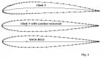
The NACA took several of the better airfoils of the time, such as the Clark Y and the Göttingen 398 and discovered that when the camber was removed and they were scaled to the same thickness, all were essentially identical³. See Fig. 1.
The resulting basic section is the NACA 0012 which can be defined mathematically and can easily be scaled to any thickness by changing the constants in an equation. The effects of thickness and camber were thus separated and a systematic cataloging system could be applied; sort of a Dewey Decimal System for airfoils.
The first integer indicates the maximum camber of the mean line in percent of chord and the second the location of maximum camber from the leading edge in tenths of chord. The last two integers indicate the thickness in percent of chord. The meanlines used with NACA 4 digit airfoils are also mathematically defined.
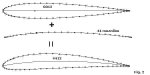
Thus the NACA 4412, an excellent airfoil for fixed wing aircraft, having very high maximum lift combined with benign stall behavior, has a maximum camber of 4% of chord located at 4 tenths of chord from the leading edge. Thickness is obviously 12% of chord. Refer to figure 2.
Rotating wings
Rotor blades, unlike fixed wings and propeller blades are long and thin and are by nature, torsionally flexible. Highly cambered airfoils that work well for propeller blades would be disastrous if used for a rotor.
Referring to the 44 meanline of Fig. 2, the shape resembles a venetian blind slat. It would try to twist nose down when moving through the air at high speed, having a high negative pitching moment coefficient of nearly –0.1.
From the published airfoil coefficients the twisting force can be calculated:
Moment = (p*V²/2)*Area*Chord*Moment coefficient
P =air density, .0023 at sea level
V = velocity, fps
The result will be ft-lb. of twisting moment.
Blades of 7inch chord using an NACA 4412 airfoil would have a nose down moment on almost 33 ft-lb. if the tip speed was 400 fps on a 23-ft. diameter rotor. At high speed such a machine would most likely enter an unrecoverable dive, depending upon the torsional flexibility of the blades.
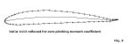
An NACA 4412 airfoil could be used for rotorblades if the trailing edge was given a reflex; i.e., an upswept trailing edge that serves the same purpose as an up elevator. Considerable reflex is necessary, reducing maximum lift and increasing drag, negating the advantage of high camber. Figure 3 shows a 4412 reflexed for zero pitching moment coefficient. Flying wings also require airfoils with zero pitching moment coefficients.
The shape of the meanline determines the pitching characteristic and angle of zero lift of an airfoil as well as having considerable influence on the nature of its stall.
Aerodynamic center
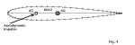
The aerodynamic center of an airfoil, the point where all aerodynamic force can be considered to act is at or near ¼ chord from the leading edge for most airfoils. For a rotorblade, which is subjected to rapidly varying aerodynamic force, the load can be thought of as striking the airfoil at its ¼ point with a rubber sledgehammer. Refer to Fig. 4.
If the rotorblade is tail heavy, that is if the CG is aft of the ¼ chord point, the blade coming into the wind is subjected to a nose up impulse which tends to become self sustaining; the more it twists nose up, the heavier the aerodynamic blow. If sufficiently tail heavy, the blade will flutter. If not sufficiently tail heavy for flutter to occur, the rotor will simply be unstable Vs. angle of attack. An upward gust will cause the rotor to increase its angle of attack, described by pilots flying such rotors as “ballooning.”
Conversely, overbalancing a blade so as to locate its CG ahead of the ¼ chord point can enhance the stability of a rotor. Excessive overbalance of a torsionally flexible blade can produce a rotor so stable that it won’t respond to anything, including cyclic control input. But it’s nearly impossible to grossly overbalance a rotor with internal weights; external nose weights would be required.
Cierva’s rotorblades
The very earliest phase of Autogiro development involved about as much art as science. Cierva had to play it by ear as he developed the science.
The first Autogiro to fly employed an Eiffel 106 airfoil that was apparently a symmetrical section that I’ve been unable to locate in a brief Internet search.
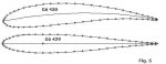
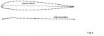
Next was a Göttingen 430, a highly cambered airfoil with a strong negative pitching characteristic that was believed to have caused one machine to have shed a blade as a result of the periodic twisting of the spar.
After that, Cierva standardized on the Gö 429 airfoil for several years. The 429 is a nearly symmetrical airfoil with performance about equal to an NACA 0012. The Gö 429 and 430 are shown in Fig 5.
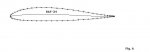
After that, around 1930, the RAF 34 airfoil was tried. The RAF 34 is a mildly cambered, reflexed airfoil that appears to have been developed specifically for use as a rotorcraft airfoil. It looks pretty good on a computer airfoil analysis program but apparently didn’t suit Cierva. See figure 6.
With the introduction of the direct control C-30, Cierva switched to a Gö-606 airfoil as did Pitcairn and Kellett in the US. I’ve not been able to locate a drawing of the Gö-606 but have seen it on a couple of examples of C-30s. It is a mildly cambered airfoil, somewhat resembling an RAF-34 but without trailing edge reflex. It has a bit of negative pitching moment coefficient and at least one C-30 was lost in a high speed dive where it was possible to run out of rearward stick travel. The periodic twisting of airfoils with negative pitching moment coefficient amounts, in effect, to a built in swashplate that tilts the rotor disc nosedown.
Airfoils with nosedown pitching characteristics can also lead to unstable stick position gradient vs. airspeed. With correctly designed airfoils, the stick position will move forward as airspeed increases.
The problem of negative moment coefficient was addressed by fitting upturned TE trim tabs that extended over the outer 1/3 of the blade radius on the Kellett KD-1s and later models of the C-30.
The very last Autogiros, produced just before WWII halted production, utilized the NACA 23012 airfoil. See Fig. 7.
The 23012 employs the 0012 thickness distribution combined with a meanline very different from that of the 4 digit series.
Testing by the NACA of the 4 digit series of airfoils showed that maximum lift was increased as the location of maximum camber was shifted either ahead of or aft of mid chord. Rearward location of maximum camber isn’t of much interest because of the large increase of pitching moment coefficient. A location of maximum camber near the leading edge (a droop nose) produces a large increase of maximum lift with a minimal effect on pitching moment coefficient.
To exploit the advantages of forward camber location, the NACA adopted a 5 digit designation system to supplement the 4 digit family. The thickness distribution is the same but a new series of meanlines was developed; the 210, 220, 230, 240, etc. meanlines.
The first integer indicates the design lift coefficient as 3/2 of design lift expressed as tenths, i.e., if the first integer is 2, the design lift coefficient is 0.3. Clever, no? The second two integers together indicate the location of maximum camber from the leading edge as twice its actual location expressed as a percentage. Thus, the 210 meanline has maximum camber located at 5% of chord from the leading edge; the 230 meanline has maximum camber at 15% of chord and so on. The meanline of these airfoils is a straight line from just aft of maximum camber to the trailing edge.
The 23012 is an excellent rotor airfoil for gyros, having high maximum lift and low drag. It has a negative pitching moment coefficient of
–0.014, so slight that in most cases it can be ignored. But hand starting would be difficult due to the abrupt stall characteristic.
The Bensen Era
Bensen began with plywood blades of NACA 0012 airfoil section but hand starting was difficult and he wanted an airfoil with flat surfaces to simplify construction for homebuilders. He evolved what he called the Bensen G-2 airfoil to address both problems.
The Bensen G-2 rotorblades had a meanline resembling the NACA 240 or 250 series and used flat plywood skins aft of the ¼ chord point or so. The trailing edge was reflexed by beveling the lower skin, however, the reflex was in excess of the amount required for zero moment coefficient but served the intended purpose well.
Excess reflex of plywood blades makes hand starting a snap. Mount the blades to the hub with very low incidence and as the rotor comes up to speed, the blades automatically twist nose up to the proper flying pitch. Excess reflex also tends to limit top speed; the flapping angle increases at a rate that will cause the cyclic stick to reach its forward stop at slightly more than 60 mph.
The two gyroplanes that were certificated during the Bensen Era, the A&S 18-A and the McCulloch J-2 both used symmetrical airfoil rotorblades; the 18-A used NACA 0012s and the J-2 used NACA 0015s. Probably the main reason for using symmetrical rotorblades was availability but in the case of the 18-A at least, the 0012 isn’t a bad airfoil. The 0015 is a bit draggy but I and many others in Florida flew military surplus (runouts) Hughes-269 (TH-55) and Hughes OH-6 NACA-0015 blades for hundreds, perhaps thousands of hours. They were at least as good as the contemporary metal rotorblades but hand starting wasn’t an option.
Bensen eventually switched over to metal blades using an airfoil patterned after the NACA 8H12. The H stands for helicopter and they’re 12% thick. See Fig. 7.
The NACA began investigating laminar airfoils in about 1940, possible only after wind tunnels of extremely low turbulence levels had been developed. It’s not just bugs that upset laminar flow but airstream turbulence as well. Laminar airfoils have a sharper nose than standard airfoils and maximum thickness is located farther aft.
The 8H12 was developed with the hope of improving the performance of early helicopters but it was a failure. The 0012 develops higher lift before stall, has no more real world drag and is easier to fabricate.
But the 8H12 is adequate for gyros, especially if hand starting is a requirement. The stall is fairly benign; gradual rather than abrupt. The nature of stall of a rotorblade airfoil determines whether or not it can be hand started but is not a safety issue; the inner portions of the retreating blade are always stalled with the stall spreading outward as the airspeed increases. The NACA conducted photographic studies of stall on the retreating blade of a Kellett KD-1 Autogiro with airspeed sufficient to stall as much as 60% of the blade.
Bensen modified the 8H12 by flattening the lower surface. The Bensen lower skin is 0.05” thick and serves as a redundant load path.
The thing that degraded performance of Bensen metal blades the most was the use segmented skins on the upper surface. Flapwise flexibility of rotorblades is desirable as it reduces stress and provides a smoother ride but the gaps between skin segments ought to be sealed. Otherwise, a rotor blade becomes a centrifugal pump and can consume several HP needlessly pumping air.
A thread covering this paper is here:
http://www.rotaryforum.com/forum/showthread.php?t=45756
Please post any questions to this thread in the "Theory of Flight" section.
¹)Osborne Reynolds, 1842-1912. British physicist, mathematician and pioneer in the field of fluid mechanics.
²)National Advisory Committee for Aeronautics. Established by Congress in 1915 and superceded by NASA in 1958.
³)There is a wealth of airfoil data on the University of Illinois website:
http://m-selig.ae.illinois.edu/ads/coord_database.html
“As an inviscid and incompressible fluid flows, the total head remains unchanged,” so said Bernoulli in adapting the conservation of energy law to fluid flow. That means, in plain English, that without friction, energy of a fluid stream is conserved. But poor Bernoulli gets mangled by the aviators.
The end purpose of all airfoils is to change the direction, or more explicitly, the momentum of a moving airmass with a minimum of friction loss.
Momentum is the product of mass and velocity; it is a vector quantity, meaning that it has direction. To an airplane, the airstream has horizontal momentum and to produce the reaction we call lift, some of the oncoming airmass must be given a downward momentum. Lift is the same kind of phenomenon as the recoil of a shotgun.
In the beginning
Kites and windmills date back into antiquity. It seems not unlikely that the Chinese had man-carrying kites. But it’s only been during the past century or so that we’ve gradually acquired a quantitative understanding of how such things work.
Sir Isaac Newton appears to have been among the first to have attempted a scientific analysis of a flying machine but his assumptions were wrong. He assumed that only the air intercepted by the lifting surface resulting from its angle of attack (tangent of angle of attack times chord) would be given a downward momentum. He failed to appreciate that at subsonic speed, air is an incompressible fluid* that behaves similarly to water. The air far above and far below the lifting surface is also affected. Newton’s wings would have been impossibly large for any practical application.
*Air is incompressible in the context of subsonic flow over airfoils. I have heard of air compressors.
The early aviation experimenters began with flat plate wings but soon realized that curvature improved efficiency; influenced most likely by the observation of birds’ wings.
The Wright Brothers built their own wind tunnel and systematically explored many airfoil shapes but were mislead by being unaware of the effect of scale. Big wings behave very differently than little wings at the same airspeed.
We allow for the effect of scale by applying a factor called the Reynolds¹ number; the chord in feet multiplied by the velocity in fps multiplied by 6378 for standard sea level air density. Rotorblade tips operate at a Reynolds number in the range of 1 to 2 million.
The Wright Brothers were conducting their research at very low Reynolds numbers where flow is always laminar and thin airfoils perform better than thick airfoils. Folded paper airplanes wouldn’t fly as well with thick wings.
Later developments
As governments and universities began taking an interest in aeronautics and came online with wind tunnels that eventually operated at more realistic Reynolds numbers, it was discovered that thicker is better, at least up to a thickness of about 12%. A 12% thick airfoil gives the best ratio of maximum lift divided by minimum drag. Many airplanes have wings thicker than 12% but this is for structural rather than aerodynamic reasons.
The early government and university wind tunnels were initially stuck in the same low Reynolds number realm as the Wright Brothers. To achieve full scale Reynolds numbers either very large airfoil sections must be tested or small scale sections must be tested at very high airspeed, neither an attractive option. The NACA² solved this dilemma by developing pressurized wind tunnels that could be operated at pressures of 25 atmospheres or more. Reynolds number increases directly with air density.
The NACA also brought order to the chaos that resulted from everyone jumping on the airfoil bandwagon. Laboratories in Germany, France, Italy, the UK, the US and elsewhere tested a multitude of airfoils that were assigned numbers that had no meaning other than being a sequence number.
The NACA took several of the better airfoils of the time, such as the Clark Y and the Göttingen 398 and discovered that when the camber was removed and they were scaled to the same thickness, all were essentially identical³. See Fig. 1.
The resulting basic section is the NACA 0012 which can be defined mathematically and can easily be scaled to any thickness by changing the constants in an equation. The effects of thickness and camber were thus separated and a systematic cataloging system could be applied; sort of a Dewey Decimal System for airfoils.
The first integer indicates the maximum camber of the mean line in percent of chord and the second the location of maximum camber from the leading edge in tenths of chord. The last two integers indicate the thickness in percent of chord. The meanlines used with NACA 4 digit airfoils are also mathematically defined.
Thus the NACA 4412, an excellent airfoil for fixed wing aircraft, having very high maximum lift combined with benign stall behavior, has a maximum camber of 4% of chord located at 4 tenths of chord from the leading edge. Thickness is obviously 12% of chord. Refer to figure 2.
Rotating wings
Rotor blades, unlike fixed wings and propeller blades are long and thin and are by nature, torsionally flexible. Highly cambered airfoils that work well for propeller blades would be disastrous if used for a rotor.
Referring to the 44 meanline of Fig. 2, the shape resembles a venetian blind slat. It would try to twist nose down when moving through the air at high speed, having a high negative pitching moment coefficient of nearly –0.1.
From the published airfoil coefficients the twisting force can be calculated:
Moment = (p*V²/2)*Area*Chord*Moment coefficient
P =air density, .0023 at sea level
V = velocity, fps
The result will be ft-lb. of twisting moment.
Blades of 7inch chord using an NACA 4412 airfoil would have a nose down moment on almost 33 ft-lb. if the tip speed was 400 fps on a 23-ft. diameter rotor. At high speed such a machine would most likely enter an unrecoverable dive, depending upon the torsional flexibility of the blades.
An NACA 4412 airfoil could be used for rotorblades if the trailing edge was given a reflex; i.e., an upswept trailing edge that serves the same purpose as an up elevator. Considerable reflex is necessary, reducing maximum lift and increasing drag, negating the advantage of high camber. Figure 3 shows a 4412 reflexed for zero pitching moment coefficient. Flying wings also require airfoils with zero pitching moment coefficients.
The shape of the meanline determines the pitching characteristic and angle of zero lift of an airfoil as well as having considerable influence on the nature of its stall.
Aerodynamic center
The aerodynamic center of an airfoil, the point where all aerodynamic force can be considered to act is at or near ¼ chord from the leading edge for most airfoils. For a rotorblade, which is subjected to rapidly varying aerodynamic force, the load can be thought of as striking the airfoil at its ¼ point with a rubber sledgehammer. Refer to Fig. 4.
If the rotorblade is tail heavy, that is if the CG is aft of the ¼ chord point, the blade coming into the wind is subjected to a nose up impulse which tends to become self sustaining; the more it twists nose up, the heavier the aerodynamic blow. If sufficiently tail heavy, the blade will flutter. If not sufficiently tail heavy for flutter to occur, the rotor will simply be unstable Vs. angle of attack. An upward gust will cause the rotor to increase its angle of attack, described by pilots flying such rotors as “ballooning.”
Conversely, overbalancing a blade so as to locate its CG ahead of the ¼ chord point can enhance the stability of a rotor. Excessive overbalance of a torsionally flexible blade can produce a rotor so stable that it won’t respond to anything, including cyclic control input. But it’s nearly impossible to grossly overbalance a rotor with internal weights; external nose weights would be required.
Cierva’s rotorblades
The very earliest phase of Autogiro development involved about as much art as science. Cierva had to play it by ear as he developed the science.
The first Autogiro to fly employed an Eiffel 106 airfoil that was apparently a symmetrical section that I’ve been unable to locate in a brief Internet search.
Next was a Göttingen 430, a highly cambered airfoil with a strong negative pitching characteristic that was believed to have caused one machine to have shed a blade as a result of the periodic twisting of the spar.
After that, Cierva standardized on the Gö 429 airfoil for several years. The 429 is a nearly symmetrical airfoil with performance about equal to an NACA 0012. The Gö 429 and 430 are shown in Fig 5.
After that, around 1930, the RAF 34 airfoil was tried. The RAF 34 is a mildly cambered, reflexed airfoil that appears to have been developed specifically for use as a rotorcraft airfoil. It looks pretty good on a computer airfoil analysis program but apparently didn’t suit Cierva. See figure 6.
With the introduction of the direct control C-30, Cierva switched to a Gö-606 airfoil as did Pitcairn and Kellett in the US. I’ve not been able to locate a drawing of the Gö-606 but have seen it on a couple of examples of C-30s. It is a mildly cambered airfoil, somewhat resembling an RAF-34 but without trailing edge reflex. It has a bit of negative pitching moment coefficient and at least one C-30 was lost in a high speed dive where it was possible to run out of rearward stick travel. The periodic twisting of airfoils with negative pitching moment coefficient amounts, in effect, to a built in swashplate that tilts the rotor disc nosedown.
Airfoils with nosedown pitching characteristics can also lead to unstable stick position gradient vs. airspeed. With correctly designed airfoils, the stick position will move forward as airspeed increases.
The problem of negative moment coefficient was addressed by fitting upturned TE trim tabs that extended over the outer 1/3 of the blade radius on the Kellett KD-1s and later models of the C-30.
The very last Autogiros, produced just before WWII halted production, utilized the NACA 23012 airfoil. See Fig. 7.
The 23012 employs the 0012 thickness distribution combined with a meanline very different from that of the 4 digit series.
Testing by the NACA of the 4 digit series of airfoils showed that maximum lift was increased as the location of maximum camber was shifted either ahead of or aft of mid chord. Rearward location of maximum camber isn’t of much interest because of the large increase of pitching moment coefficient. A location of maximum camber near the leading edge (a droop nose) produces a large increase of maximum lift with a minimal effect on pitching moment coefficient.
To exploit the advantages of forward camber location, the NACA adopted a 5 digit designation system to supplement the 4 digit family. The thickness distribution is the same but a new series of meanlines was developed; the 210, 220, 230, 240, etc. meanlines.
The first integer indicates the design lift coefficient as 3/2 of design lift expressed as tenths, i.e., if the first integer is 2, the design lift coefficient is 0.3. Clever, no? The second two integers together indicate the location of maximum camber from the leading edge as twice its actual location expressed as a percentage. Thus, the 210 meanline has maximum camber located at 5% of chord from the leading edge; the 230 meanline has maximum camber at 15% of chord and so on. The meanline of these airfoils is a straight line from just aft of maximum camber to the trailing edge.
The 23012 is an excellent rotor airfoil for gyros, having high maximum lift and low drag. It has a negative pitching moment coefficient of
–0.014, so slight that in most cases it can be ignored. But hand starting would be difficult due to the abrupt stall characteristic.
The Bensen Era
Bensen began with plywood blades of NACA 0012 airfoil section but hand starting was difficult and he wanted an airfoil with flat surfaces to simplify construction for homebuilders. He evolved what he called the Bensen G-2 airfoil to address both problems.
The Bensen G-2 rotorblades had a meanline resembling the NACA 240 or 250 series and used flat plywood skins aft of the ¼ chord point or so. The trailing edge was reflexed by beveling the lower skin, however, the reflex was in excess of the amount required for zero moment coefficient but served the intended purpose well.
Excess reflex of plywood blades makes hand starting a snap. Mount the blades to the hub with very low incidence and as the rotor comes up to speed, the blades automatically twist nose up to the proper flying pitch. Excess reflex also tends to limit top speed; the flapping angle increases at a rate that will cause the cyclic stick to reach its forward stop at slightly more than 60 mph.
The two gyroplanes that were certificated during the Bensen Era, the A&S 18-A and the McCulloch J-2 both used symmetrical airfoil rotorblades; the 18-A used NACA 0012s and the J-2 used NACA 0015s. Probably the main reason for using symmetrical rotorblades was availability but in the case of the 18-A at least, the 0012 isn’t a bad airfoil. The 0015 is a bit draggy but I and many others in Florida flew military surplus (runouts) Hughes-269 (TH-55) and Hughes OH-6 NACA-0015 blades for hundreds, perhaps thousands of hours. They were at least as good as the contemporary metal rotorblades but hand starting wasn’t an option.
Bensen eventually switched over to metal blades using an airfoil patterned after the NACA 8H12. The H stands for helicopter and they’re 12% thick. See Fig. 7.
The NACA began investigating laminar airfoils in about 1940, possible only after wind tunnels of extremely low turbulence levels had been developed. It’s not just bugs that upset laminar flow but airstream turbulence as well. Laminar airfoils have a sharper nose than standard airfoils and maximum thickness is located farther aft.
The 8H12 was developed with the hope of improving the performance of early helicopters but it was a failure. The 0012 develops higher lift before stall, has no more real world drag and is easier to fabricate.
But the 8H12 is adequate for gyros, especially if hand starting is a requirement. The stall is fairly benign; gradual rather than abrupt. The nature of stall of a rotorblade airfoil determines whether or not it can be hand started but is not a safety issue; the inner portions of the retreating blade are always stalled with the stall spreading outward as the airspeed increases. The NACA conducted photographic studies of stall on the retreating blade of a Kellett KD-1 Autogiro with airspeed sufficient to stall as much as 60% of the blade.
Bensen modified the 8H12 by flattening the lower surface. The Bensen lower skin is 0.05” thick and serves as a redundant load path.
The thing that degraded performance of Bensen metal blades the most was the use segmented skins on the upper surface. Flapwise flexibility of rotorblades is desirable as it reduces stress and provides a smoother ride but the gaps between skin segments ought to be sealed. Otherwise, a rotor blade becomes a centrifugal pump and can consume several HP needlessly pumping air.
A thread covering this paper is here:
http://www.rotaryforum.com/forum/showthread.php?t=45756
Please post any questions to this thread in the "Theory of Flight" section.
¹)Osborne Reynolds, 1842-1912. British physicist, mathematician and pioneer in the field of fluid mechanics.
²)National Advisory Committee for Aeronautics. Established by Congress in 1915 and superceded by NASA in 1958.
³)There is a wealth of airfoil data on the University of Illinois website:
http://m-selig.ae.illinois.edu/ads/coord_database.html
Attachments
Last edited by a moderator: