quoj
Newbie
- Joined
- May 1, 2011
- Messages
- 35
- Location
- Brisbane
- Aircraft
- Jabirus LSA, Tecnam Golf, Tecnam Super Echo
- Total Flight Time
- Approx 180hrs FW Gliders. Approx 100 hrs FW Powered
Hi all,
Another dumb newbie question.
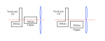
I know about thrust lines and the rule-of-thumb that the thrust line should be somewhere close to going through the pilot's navel.
(I also know that it's not as simple as that and that the weight of the aircraft, weight of the pilot, centre of gravity and centre of mass all play a calculated part in determining where the centreline actually is.)
I know that having a dropped-keel (like the Dominator/Butterfly/Ultrawhite/etc) allows you to lower the level of the engine, and thus the thrust-line.
I know that a reduction drive pointed downwards can lower this thrust line even further.
I know that a larger, slower prop is actually better that a smaller, faster prop.
I have heard a number of people claim that the standard Benson/Brock design is actually close to Centreline Thrust.
How can this be if other designs require a significantly dropped keel to allow achieve such a low thrust line?
I saw a video on Youtube by a guy named "Gyroflight" (I'm guessing that it's one of you guys) entitled "Mangnolia Pt 1".
http://www.youtube.com/user/Gyroflight#p/a/u/0/mQJFAAJZe6w
At approximately the 6:11 mark, there is visible, what appears to be a regular Bensen/Brock design without any form of drop-keel arrangement yet still adheres to the "thrust line through the pilot's navel" rule.
How is this achieved?
Is the prop smaller?
I'm guessing that it's direct drive with no reduction drive?
At what cost does this come?
Also, there is a rather interesting Tractor machine at the 2:12 mark supposedly owned by "Virgil". Is this a one-off or a kit design?
Is this an effective design that is worth replicating should one wish to go with a tractor model?
Thanks in advance.
Another dumb newbie question.
I know about thrust lines and the rule-of-thumb that the thrust line should be somewhere close to going through the pilot's navel.
(I also know that it's not as simple as that and that the weight of the aircraft, weight of the pilot, centre of gravity and centre of mass all play a calculated part in determining where the centreline actually is.)
I know that having a dropped-keel (like the Dominator/Butterfly/Ultrawhite/etc) allows you to lower the level of the engine, and thus the thrust-line.
I know that a reduction drive pointed downwards can lower this thrust line even further.
I know that a larger, slower prop is actually better that a smaller, faster prop.
I have heard a number of people claim that the standard Benson/Brock design is actually close to Centreline Thrust.
How can this be if other designs require a significantly dropped keel to allow achieve such a low thrust line?
I saw a video on Youtube by a guy named "Gyroflight" (I'm guessing that it's one of you guys) entitled "Mangnolia Pt 1".
http://www.youtube.com/user/Gyroflight#p/a/u/0/mQJFAAJZe6w
At approximately the 6:11 mark, there is visible, what appears to be a regular Bensen/Brock design without any form of drop-keel arrangement yet still adheres to the "thrust line through the pilot's navel" rule.
How is this achieved?
Is the prop smaller?
I'm guessing that it's direct drive with no reduction drive?
At what cost does this come?
Also, there is a rather interesting Tractor machine at the 2:12 mark supposedly owned by "Virgil". Is this a one-off or a kit design?
Is this an effective design that is worth replicating should one wish to go with a tractor model?
Thanks in advance.
Last edited: