Aerodynamic Efficiency: Puller Propeller verses Pusher Propeller?

>This implies that having two coaxial actuator disks directing their efflux at each other can represent ground effect and thereby improve the efficiency of both disks.

are you saying...

___v___+____v____ (clockwise)

___^___+____^___ (anti-clockwise- artificial ground effect)

...with the arrows representing the flow direction? If so you're pushing yourself up by your own bootstraps- conservation of energy .. the lower rotor is throwing mass up so the reaction is down thrust.

How about this...

___v___+____v____ (clockwise)
(F)(E)​
__v___+___v__ (anti-clockwise- rotor 2)

Where F is fuel and E is an engine of sufficient horse power (http://www.recpower.com/f33.htm) ... Rotor 2 can/will rotate at some speed in relationship to rotor 1 with the net effect being to cancel the torque of rotor 1. Fixed blade incidence and diameter the rotors would be chosen to maximize thrust in the normal flight range. By increasing the velocity of the same mass of inflow air to the sum of the interacting rotors the thrust developed by a coaxial rotor is increased. This ignores the actual interaction of two airscrews in close proximity- there was a gyro that had a pair of counter-rotating props and the results in terms of noise, thrust, weight, and complexity.

The only control input through the rotorhead is throttle but if you wanted to know how the engine was doing, what the fuel level was, etc you would need to pass a info throgh a rotating U-joint. No idea if coaxial rotors or other exotics behave well when it comes to autorotation so what happens if your engine fails?

While you could use cyclic pitch feathering or Kaman servo tabs on the lower rotor to control rotor thrust that probably isn't required; without engine torque applied to the airframe you could apply cyclic by tilting the hub which wouldn't require a complex swashplate.

Of course if it's all that great you gotta wonder why everybody isn't flying a Bendix ... http://www.goantiques.com/detail,bendix-helicopter-1946,337513.html ... at least the stock isn't worthless; just need to hold on to it long enough. :)
 
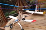
Here's a coaxial R/C gyro I spotted on an R/C forum.

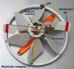
Another one, http://tinyurl.com/eaeg9 uses an idea along the lines of what Larry is talking about-sort of.
It counters the torque of the bottom mounted rotor by allowing the saucer shaped body to spin. The body has vanes which contribute to lift.
The trick is how to control the thing and the solution was to mount a sensor on the edge of the spinning body that detects the earth's lines of magnetic flux and thus it can figure out where it is pointed at any instant. From there it can be determined how to phase the control inputs to the hiller type paddles. An onboard controller handles all the figurin'
 

Attachments

  • coaxial_RC_gyro.jpg
    coaxial_RC_gyro.jpg
    69.3 KB · Views: 0
  • UFO.jpg
    UFO.jpg
    24.4 KB · Views: 0
Last edited:
Larry,

I should have stated it more clearly. Ga6riel says it best.

Here is a different way of considering mirror image thrust. Consider a person who is standing in front of a secure plywood wall. His hands are on the wall and he is pushing against the wall with 50 lbs of force.

Now replace the plywood with a mirror. It now looks like he, and his mirror image, are pushing against each other with 50 lbs of force each.

Now replace the mirror with plate glass and replace the mirror image with another person. It now looks like he, and this other person, are pushing against each other with 50 lbs of force each.

Now remove the mirror. He, and this other person, ARE pushing against each other with 50 lbs of force each.

In other words pushing against the ground (wall) is the same as pushing against an identical rotor (person).

_______________

Al;

Interesting.
_______________

Mart

Since Larry has mentioned coaxial rotors, Al is talking coaxial, and we have previously discussed the efficiency of coaxial rotors versus independent rotors, this linked postings, sketch, and associated information may clear up the subject.

Dave
 
Dave, two skydivers, doing pushups on one another are still both going to be falling. I think the idea of reflected airstreams in ground effect is not the same as saying that lift force is reflected. It is saying that drag is reduced for the same lift and collective can be lowered.
When you think about it, all forces are reflected in the sense that there is an opposite reaction to every action. Rocket exhaust pushes the rocket up while it pushes down on the launch pad. The pad is pushing up. Forces appear in pairs.
A rotor in ground effect is pushing down on the ground. The ground pushes back. It happens that the ground is made up of the planet earth and has a huge mass compared to the aircraft. Thus the earth doesn't seem to move.
If the rotorcraft hovered over a planet with the same mass as itself, it would push it away and lift would cease when the atmosphere went with it.
You don't seriously think that having coaxial rotors thrusting at each other would be capable of lifting anything?
 
Opps, I really did not explain it very well. At least Ga6riel got it. ~ I think.

You don't seriously think that having coaxial rotors thrusting at each other would be capable of lifting anything?
No. This is not a case of a craft having two real rotors, which are thrusting at each.other.

This is a case of;

~ The resistance of ground effect will increase the efficiency (efficiency to push air) of one real rotor.

~ A 'mirror image' rotor could 'theoretically' be substituted for the ground. Whereby the efficiency of the real rotor would be the same as if the ground was still there.

~ This means that the 'mirror image' rotor improves the efficiency of the real rotor, and the 'mirror image' rotor will have the same efficiency as the real rotor.

Now, move the 'mirror image' rotor 90-degrees, from under the craft to pointing forward, so that the two rotors no longer have a common axis (are no longer coaxial) and replace the 'mirror image' rotor with a real tractor propeller.

The real rotor and the real tractor propeller are thrusting air into the same space. Therefore, for the reason given above, the air in this space will increase the efficiency of both the real rotor and the real propeller.

Of course this increase in the efficiency will not be as good is it would be if the two actuator disks were pushing air directly at each other (i.e. if they had a common axis).
_________________________

However, the efficiency will be better than if a pusher propeller was used instead of the tractor propeller, because the tractor propeller will be removing air from under the rotor
__________________________

Any disagreement? :)

Dave
 
Last edited:
Dave, I am not following the subtleties of your argument, I guess. Sorry.

Addressing an earlier point; If the tractor prop is somehow pressurizing the air under the rotor, and assuming for the moment that this makes the rotor work better, wouldn't that subtract from the ability of the prop to provide thrust?
Some of the power of the prop is diverted into compressing air rather than accelerating it out the back.
When you propose concepts like the air having "difficulty getting out of the way" it makes me think we should be using more exacting terminology so we're not trying to nail jello to the wall.
 
hmmm well
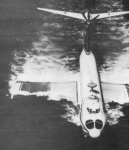
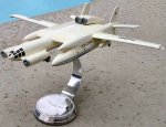
with the GEV Sukhoi Orlyonok the russians perfected an idea they tagged PAR
Power Augmented Ram. this machine compares with a 727 in size

the idea was this, that rather mighty nose mounted engines would force thrust air beneath the mainplane aiding:

1 unsticking the flying boat form from the surface,
2 an amount of STOL capability,
3 an amount of hover capability

two spherical jet eflux mounts, one either side of the nose, could direct thrust air roughly 80 degrees down, or 0 degrees aft.

from the math implied, thrust vectored beneath the wing accomplished all 3 points and, at ideal vectors contributed to forward motion and 80% of the force became forward thrust, AFTER the trailing edge of the mainplane released itself from the sea surface, and incrementaly as the machine climbed.

when a suitable flying speed was reached, the nozzles directed thrust air above the wing, in an effort to reduce pressure on the upper surface of the mainplane. at which point the balance of the machine stabilised, and the forward engines could be run through shutdown and be left to fly on the power of the tail mounted NK12 contra turbprop

lift was certainly enhanced by the addition of these forward engines, and i always figured that they only shut them down, when the colliding vector of forward speed would begin to disintegrate the thrust force vector and start to interfere with the leading edge of the mainplane. the PAR program was so successful it appears in various forms on roughly half the GEV's created. 90% of them would be russian in origin
 

Attachments

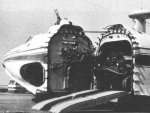
  • orlyonoc touchdown.jpg
    orlyonoc touchdown.jpg
    35.6 KB · Views: 0
  • orlyonoc beached.jpg
    orlyonoc beached.jpg
    53.6 KB · Views: 0
  • Orlyonoc open.jpg
    Orlyonoc open.jpg
    18.6 KB · Views: 0
  • orlyonoc step taxi.jpg
    orlyonoc step taxi.jpg
    22.5 KB · Views: 0
Wow, those Russians come up with some outrageous vehicles, don't they?
I wonder if Chuck Ellsworth could fly that thing and let us know if the thrust offset compares favorably with an RAF? Of course, that's a helluva stab on the back.

Ga6riel, I notice you said that the air is blown over the wing in flight, not under. This doesn't help Dave's argument, but maybe I 'm not getting it.
 
your right Al, your not getting it

thrust air is forced in the space below the wing and above the surface to vitually blow the machine off the deck

as speed increases to a safe flying speed, spherical bearings at the rear of the engines straighten the flow of thrust air so that it then passes above the wing

as its primary purpose is take off and landing, it vindicates Daves ideas

one thing about the russian programs that i admire, they are avid mathematicians and they are not affraid to put theory into reality. its an experience rather like that in the US in the late 40's and 1950's, where a diverse field of prototypes captured the collective imaginations of the populated world

included are views of the VVA 14 aka MIP, which have no traversing bearings, and thrust air clearly goes beneath the mainplane while in GE
 

Attachments

  • bartinisbizarrebehemoth.jpg
    bartinisbizarrebehemoth.jpg
    15.4 KB · Views: 0
  • 14M-1P.jpg
    14M-1P.jpg
    7.1 KB · Views: 0
  • 05134704.jpg
    05134704.jpg
    30.9 KB · Views: 0
Last edited:
>as its primary purpose is take off and landing, it vindicates Daves ideas

Doesn't take off and landing usually occur near the ground? Dave's idea as I see it so far is that a prop pointing it's backwash at another prop increases the efficiency of the second prop; maybe so but if the two are mechanically connected then any increase is lost in "the equal and opposite reaction" place. Any other loss at all for this zero sum game results in overall lower efficiency.

Dave- if I'm not getting it you need to tell me how you can direct the mass of air where you want it without generating a thrust vector pointing at the ground. A gyrodyne, for example, uses the second prop for horizontal movement- the tail rotor pulls.

Sorry for going off topic; back to pneumaticly driven reactionless rotors...
 
well this is where it gets tricky isnt it
yes it operates near the ground
it also operates with unmistakeably positive AoA
the presence of the ground enhances the lift effect/reduces drag
this is not to say it doesnt work in free space too

notice that in late WW2, most bombers began to shift to clean upper surfaces and underslung engines, while there are other reasons to support why they did this, it was noticed on development avro lancasters, that there was an increase in lift performance when the engines went underslung
 
Larry.

Thanks for continuing to question the argument, 'cause that is what the thread is all about.

Perhaps this might help;

You said;
" Dave's idea as I see it so far is that a prop pointing it's backwash at another prop increases the efficiency of the second prop; maybe so but if the two are mechanically connected then any increase is lost in "the equal and opposite reaction" place. Any other loss at all for this zero sum game results in overall lower efficiency."
Referring to the sketch on the first posting; the craft will never have two props at the same time, The tractor prop and the pusher prop are alternatives to each other.


We know that a lower temperature has a higher air density and we know that a lower elevation has a higher air density. We also know that a higher air density improves the efficiency of rotors and propellers. My belief, which could be right or wrong, is that a tractor prop combined with the rotor will increase the air density in the area behind the tractor prop and below the rotor, hence improved efficiency.

Dave
 
Gosh this thread has taken off! Some points that perhaps need clearing up.

The ground effect should only be thought of as a reflection from the point of view of flow sources. The flow will alter, but this is a complex 3D flow so can only be guestimated without CFD/testing. The ground effect does make the rotor outflux more difficult, but only in that the velocity goes down. There is pressure across the rotor and prop "disks", by bernoulli effect on blades only, but this is defined by helicopter weight or thrust so remains constant.

Dave, i agree with you that a tractor prop potentially offers improved rotor and prop efficiency. What must be stressed is that this benefit will not be the same in all flight regimes and needs to be quantified. In hover there will be no thrust so rotor efficiency is unaffected. In high speed flight the prop will be efficient (ie only small change in propwash speed) due to high mass flow rate so will generate at best a slight rotor efficiency increase.

To put the prop at the front of the rotor requires a long drive shaft past the cockpit, or a second engine. The benefit of puller prop over pusher needs to be quantified to see if it justifies the complexity increase. My guess is that by going for an oversize pusher prop, the prop flow speed can be kept close enough to overal flow that there is little advantage in additional drivetrain. From the packaging point of view i suspect that twin props (say either side of fuselage) close to rotor centre will work best. It may be time to compromise again... :)

Ga6riel, i too have a deep held respect for Russian Engineering. They seem to be good at integrating mathematicians and physicists into the technology arena. Then again the hovercraft was a British invention! ;)

Mart
 
Last edited:
Ga6riel, i too have a deep help respect for Russian Engineering. They seem to be good at integrating mathematicians and physicists into the technology arena. Then again the hovercraft was a British invention! ;)

Mart

i know thats the popular view, Sir Christopher Cockerell was the patentee, it really wasnt an effective machine until the skirt was developed by C H Latimer-Needham,

first recorded hovercraft was in 1716 by Emanuel Swedenborg, a Swedish designer, and was of course man powered.

The first practical hovercraft was in the mid 1930's, Soviet engineer Vladimir Levkov. he built about 20 of them

Edit to add; "Sir"
 
Last edited:
Mart,

As you say "[A Tractor prop] will generate at best a slight rotor efficiency increase".
For the same reasons it might be said that a Pusher prop will generate at best a slight rotor efficiency DECREASE.

This may double the advantage of Tractor over Pusher.

As the above prop location will affect the rotor efficiency, so will the rotor location affect the propeller efficiency.

This may quadruple the advantage of Tractor over Pusher.
_____________________________

Again, as you say, there are many other things to be considered.


Dave
 
>Referring to the sketch on the first posting; the craft will never have two props at the same time, The tractor prop and the pusher prop are alternatives to each other.

That's what you drew, but it's not what you said. You made this comment which is the one I was talking about.

>This implies that having two coaxial actuator disks directing their efflux at each other can represent ground effect and thereby improve the efficiency of both disks.

This says if you point the backwash of the rotor on the bottom at the bottom of the rotor on the top you improve efficiency- if that works it means you're lifting yourself up by your own boot straps. What am I missing?
 
Hi Larry,

The first quotation refers to the propeller, and where it is located.


In the second quotation "two coaxial actuator disks" means 'two rotor disks that have a common axis', but are not structurally connected in any way.

Consider a helicopter that is hovering in ground effect. Then someone pulls the ground out from under the helicopter. Lo and behold, there is a second identical helicopter bolted upside down to some structure and it's streamtube is blowing upward. The 'first helicopter is still in so-called ground effect, it is just that the effect of the up-wash of the inverted helicopter has replaced the effect of the ground. In other words, the ground can be considered as one big mirror.


Dave
 
A pusher prop always suffers thrust loss if there is disturbed air upstream
of it, so the puller prop is more efficient . i think.
 
autogyro,
so the puller prop is more efficient . i think
I think so too.

This
Farfadet.jpg

is probably more efficient than this.
H60.gif
 
Top