Explained in another way..
Explained in another way..
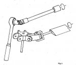
The pilot doesn't actually apply forces to tilt the rotor directly, but applies control forces that cause cyclic blade pitch changes, and those pitch changes cause lift-distribution imbalances in the spinning rotor disk which causes to rotor to tilt. So, the force to tilt a rotor is aerodynamic and comes from the airstream, not form the pilot.
I have just grasped this a few months ago - I think
")
so I would like to explain it a bit more or in another way:
Rotor blades are heavy, long and spinning fast so one would expect a big force to tilt this ‘disk´- and it does take a big force!
BUT the pilot only add the force needed to tilt the rotor blades around their long axis – the rotor head make sure, that the spinning blades are tilted back and forth a few dg. around their long axis 2 times per rev. = cyclic change of blade pitch = cyclic pitch.
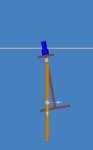
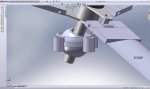
In illustration 1 the rotor head is tilted for a left turn by a little control force, and the rotor blades are perpendicular to the main frame.
At this exact position there is equal lift from each rotor blade.
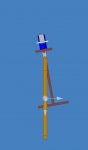
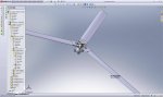
In the next 90 degree there is an increase of tilt of the rotor blades around their long axis – see illustration 2.
This tilt gives an increase of pitch on one blade, and a decrease of pitch on the other!
The result is a lower lift on the front half of the ‘disk’, and a higher lift on the back half.
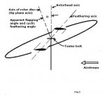
NOTE: For a spinning ‘disk´’, gyroscope, the force is in 90 degree - so the ‘disk’ tilts to the left.