Cierva rotor rpms?

Sapientino

Senior Member
Joined
Mar 14, 2005
Messages
214
Location
Lecco (Italy)
Aircraft
custom gyro
I have noticed that first autogyro had low rpms rotors, i have few questions:
how evolved gyro rpms?
would be usefull nowdays to reduce rotor rpms to increase performances?
it seems to me that autogyro from pitcairn have reduced performances because of a involution due to bensen style (I'm writing an excel file to evaluate this).
Which were precisely pitcairn/cierva rotor rpms? so low because of low disc loading?
also carter copter CGDT seems to fly with only 250 rpm instead of usual 330 rpms
someone have some avaluations on this topics
thanks to everybody
 
The 1930s Autogiros typically used rotor speed of ~200 rpm but rotor diameter was ~40 ft. which produced a tip speed of ~400 fps.

A Bensen B-8 used a rotor speed of ~360 rpm with a 22 ft. diameter which produced a tip speed of ~400 fps.

The top speed of a gyro, limited by stall of the retreating blade, is approximately 35% of rotor tip speed.

The necessary tip speed of a rotor depends upon blade loading (not disc loading). It is ~ 66 x √blade loading.

For blade loading of 40 lb/ft², it would be 417 fps.
 
The rotational speed of the rotor depends on the lift coefficient CL, rotor solidity sigma, and blade pitch angle theta. Once you have these values you can use the chart fig 2a from naca report L4H07 to find the rotational speed. I have attached the diagram.
If you assume a ratio of CL/sigma (abscissa of diagram) of 2.0 and a blade pitch angle of 4 degrees your tip speed ratio mu is roughly 0.27. An avarge gyro would then probably fly at 80 mph. the rotational speed is then
omega = v/(mu*R)
where v is the flight speed in feet per second

for a gyro with a rotor radius of 17 feet this evaluates to
omega = 117 (ft/s)*(0.27*17ft)
omega = 25.6 1/s
omega is related to rpm by n=omega/(2*pi)*60
thus n = 244 rpm

With a 34 foot rotor (17 foot diameter) tip speed is 25.6*17= 435 ft/s

This value may be 10 or 15% from the true value but playing a bit with all the parameters will give you an idea of how they influence each other

With a larger rotor (low disc loading) CL gets smaller and CL/sigma with it. A higher rotor solidity will decrease rpm via CL/sigma. Both will lead to a higher tip speed ratio mu and in turn a lower rpm since mu is in the denominator of the equation for omega. With a smaller rpm by the way the rotor is better suited for a jump start gyro.

You can find the whole report here:
http://ntrs.nasa.gov/archive/nasa/casi.ntrs.nasa.gov/19930093083_1993093083.pdf

To get familiar with the topic you might want to read this report first:
http://ntrs.nasa.gov/archive/nasa/casi.ntrs.nasa.gov/19930091561_1993091561.pdf

Cheers,

Juergen
 

Attachments

  • DiagramNacaL4H07.png
    DiagramNacaL4H07.png
    36.8 KB · Views: 0
Last edited:
The 1930s Autogiros typically used rotor speed of ~200 rpm but rotor diameter was ~40 ft. which produced a tip speed of ~400 fps.
.

thanks very much for your explanations
from the data I had found on Cierva C30 it seems that the disc loading is similar to nowdays, and they had lower rpms due to higher solidity ratio.
Is it true or I'm wrong?
then I played with Tervamaki software of gyro calculation and I noticed that increasing only blade chord from 0,18 mt to 0,4 mt for a 28ft rotor the climbing rate improves dramatically (rpm go from 370 to 250).
What do you think?
could be dangerous to reduce rpm, (having anyway standard disc loading) and same inertia at lower rpm?
thank
 
Last edited:
. With a smaller rpm by the way the rotor is better suited for a jump start gyro.
thanks for your very detailed answer (are you an aerodinamic engineer?)
You get where I want to go! I'm building a jump take off head and evaluating all aspects I get to rotor rpm.
But please (since I'm not sure) why for you a smaller rpm is better for jump start gyro? only for centrifugal force? since you need to increase blade weight in order to have same inertia at lower rpms I presume that centrifugal force will be not so lower.
I would really appreciate your considerations.
thanks
Paolo
 
are you an aerodinamic engineer?
Unfortunately not... I have worked as an FEM analyst for all German companies building railway vehicles and have gone astray right now...;-)
As to jump start that is all about the energy you are able to store in your rotor. Storing energy means to build the lightes rotor with the heaviest tip weight you can muster. So your jump start rotor could be lighter than the one you are using now, if it's cleverly designed. I'll try to come up with some figures next weekend.

Cheers for now,

Juergen
I'm a mechanical engineer too (I worked for years on engine developing)
Juergen I'll wait with impatiente your figures!
the biggest deal to build a light rotor with high mass is in my opinion the need of profile weight balance. I noticed that Carter Copter does not balace the profile but put all the mass in the end, I think this could give vibrations.
but is anyway a nice idea!
Ciao
Paolo
 
The 1930s Autogiros typically used rotor speed of ~200 rpm but rotor diameter was ~40 ft. which produced a tip speed of ~400 fps.

A Bensen B-8 used a rotor speed of ~360 rpm with a 22 ft. diameter which produced a tip speed of ~400 fps.

The top speed of a gyro, limited by stall of the retreating blade, is approximately 35% of rotor tip speed.

The necessary tip speed of a rotor depends upon blade loading (not disc loading). It is ~ 66 x √blade loading.

For blade loading of 40 lb/ft², it would be 417 fps.

Sorry Chuck at first I didn't completly understand your post
Thanks
anyway do you think it could be usefull to go little down with rpm increasing blade chord? which could be the best compromise for a jump take off gyro.
Since I see you have a huge experience in gyro, and blade building, which is the maximum twist to give a blade?
I was thinking to build a 29ft for a 450 kg gyro, with a chord of about 0,35 mt (should go to 300 rpm), and a twist of the blade at the tip (+6°??), profile? 8h12? I'm evaluating also other profiles.
What do you think?
and what about building tecniques? I was evaluating both an aluminum spar inside and glass fiber for the skin, or a unidirectional glass for spar
I would really appreciate your suggestions

thanks
Paolo
 
In my opinion, the optimization to store more energy in the rotor before jumping is a problem of centrifugal strength near the center. Conics blades are better suited to this work. So, the center of mass is nearer to the center, but this is not a disadvantage. Just a consequence.
Jean Claude
 
Sapientino/Jean Claude, the greatest power consumption of a rotor at cruise speed and above is that of profile drag; the power required to drag the rotorblade airfoil through the air. It varies as the cube power of tip speed; double the tip speed and power required is 8x as great.

The necessary tip speed varies as 1/√chord; increase chord by 2x and the tip speed decreases to 0.707x.

Put those two statements together and profile power varies as 1/chord to the 2/3 power. Double the chord and profile power decreases by 0.63x.

Bear in mind that as a general rule, a gyro won’t go much faster than ~35% of tip speed; at that speed, the stick will be on or near the forward stop and the gyro will go no faster. More power and it climbs.

If a jump could be made at an efficiency of 100%, the excess kinetic energy (IΩ² ) stored in the rotor would equal the potential energy of jump height. Alas, jumps don’t approach 100% efficiency; perhaps 20%.

A twist of 5º (tip twisted up, root twisted down) improves efficiency in autogyro flight but is detrimental during a jump where the rotor temporarily becomes a propeller. But it’s not a deal breaker.

All of Dick DeGraw’s jumpers use normal DW rotorblades except for additional tip weight.

Rotorblades: An aluminum spar with fiberglass fairing is far from optimum use of material; you have none of the fatigue resisting properties of fiberglass and obtaining a proper bond between fiberglass and aluminum requires careful chemical treatment of the aluminum spar.
 
Last edited:
Jean Claude wrote:
In my opinion, the optimization to store more energy in the rotor before jumping is a problem of centrifugal strength near the center.
Since per FAR 27 a rotor is designed for a limit maneuvering load factor of 3.5 g (which corresponds to a rotational speed of twice the operational) a jump start rpm of 1.5 times the operational will not pose a problem. The question that remains is that of how much damage is accumulated. The design goal is to incorporate a proper number of jump starts into the design life of the rotor.
 
[ how evolved gyro rpms? ]
Sapientino, I have been looking into this myself. You need to take a look at windmill theory. There were several theories on windmills and how much power they could theoreticaly extract from a moving volume of air. No doubt Cierva would have used one of these theories in his calculations. I think the Betz theory is still used today to determine the size of wind turbines.
With gyro's I think the vertical component of the airflow required through the the rotors will determine the optimal tip speed. The vertical component will also determine the twist required to keep each blade station at best angle of attack.
 
Sapientino/Jean Claude,

Chuck thanks for your very usefull suggestions, as usual very very interesting!
so I understand you suggest a undirectional fiber spar?
I wanted an alluminium spar since is more easy to calculate strenght and no problem of building defects, but I understand you are right.
Paolo
 
[ how evolved gyro rpms? ]
Sapientino, I have been looking into this myself. You need to take a look at windmill theory. There were several theories on windmills and how much power they could theoreticaly extract from a moving volume of air. No doubt Cierva would have used one of these theories in his calculations. I think the Betz theory is still used today to determine the size of wind turbines.
With gyro's I think the vertical component of the airflow required through the the rotors will determine the optimal tip speed. The vertical component will also determine the twist required to keep each blade station at best angle of attack.

very intesting considerations I'll think about it!
Paolo
 
Hi Paolo,

I had promised a few figures concerning jump take-off for the weekend and here they are
(at the bottom of this text). So what did I do? A very comprehensive investigation into
that question was carried out by J.B Wheatley and C. Bioletti in naca tn 582 titled
"Analysis and Model Tests of Autogiro Jump Take-Off" in 1936. You can find it here:
http://ntrs.nasa.gov/archive/nasa/casi.ntrs.nasa.gov/19930081354_1993081354.pdf

Friday night I started to implement the formulae of that report in a program for octave.
The code for octave is usually compatible with matlab. The program calculates the time
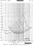
history of a jump take-off for a given initial rotor speed. In the report curves of a torque
coefficient were given for a rotor solidity of sigma= 0.1 and 0.05. I digitized these
curves and made a least square fit on them. The cq values are then interpolated between
collective pitch values theta. Currently no interpolation is performed for intermediate sigma
values.

The lift was at first calculated using a constant lift curve solpe of 6.3, a value that
is quite a bit higher than the 5.5 - 5.7 usually emplyod, yet due to the ground effect
in a jump take-off the lift will be higher than in free air. The values calculated by
the program agreed quite well with the tests for collective pitch values theta of about
10 degrees. At 16° the approximation broke down. (see below: poor agreement...) After
some tests I concluded that the lift curve solpe is grossly in error a this angle. I
had implemented a routine to calculte lift coefficient values based on data generated
with the program X-foil before. The data are for the naca 0012 profile. After incorpo-
rating this routine in the program values for larger theta are much better now.

Two things in the examples below are quite striking:
a) if rotor solidity sigma is reduced to one half (0.05 instead of 0.1) the jump height
drops from 10.5 to 0.4 feet for a certain combination of parameters. Note that
kinetic energy is not affected by this since blade inertia is calculated from mass
only.

b) a tip weight of about 10% of the blade weight increases jump height by about 35%
(from 7.8 to 10.5 feet)

The last column below (h582) gives the hight that was measured in the report. Below
that is a complete time history for an initial rotor rpm of 648 1/min. There will definitely
be errors in the values returned by the program but I think that it is more than sufficient
to explore the trend for different designs.

Cheers for now,


Juergen


sigma iBlade mBlade mTip dskLd fdgF fdgFH rpm jrpm thtaN hMax tMax h582
- [slug-ft^2] [lb] [lb] [lb/ft^2] - - [1/min] [1/min] Deg [°] [ft] [ft]
0.10080 3.11 6.00 0.00 1.06 1.0 1.0 220.00 700.00 10.00 22.8 3.8 19.5
0.10080 3.11 6.00 0.00 1.06 1.0 1.0 220.00 700.00 8.00 5.0 2.2
0.10080 3.11 6.00 0.00 1.06 1.0 1.0 220.00 650.00 10.00 12.4 3.1 12.0
0.10080 3.11 6.00 0.00 1.06 1.0 1.0 220.00 650.00 8.00 1.1 1.3
0.10080 3.11 6.00 0.00 1.06 1.0 1.0 220.00 725.00 8.00 7.8 2.5 9.4

0.10080 4.04 6.00 0.60 1.06 1.0 1.0 220.00 725.00 8.00 10.5 3.1 na
sigma reduced to one half
0.05040 4.04 6.00 0.60 1.06 1.0 1.0 220.00 725.00 8.00 0.4 1.2 na
0.10080 3.11 6.00 0.00 0.76 1.0 1.0 220.00 648.00 8.00 13.4 3.4 20.5
0.10080 3.11 6.00 0.00 1.65 1.0 1.0 220.00 700.00 8.00 0.0 0.0
0.10080 3.11 6.00 0.00 1.65 1.0 1.0 220.00 700.00 12.00 8.5 2.6 8.2
poor agreement with test data due to constant lift curve slope.
0.10080 3.11 6.00 0.00 1.65 1.0 1.0 220.00 648.00 16.00 32.5 4.3
lift curve slope reduced
0.10080 3.11 6.00 0.00 1.65 1.0 1.0 220.00 648.00 16.00 2.6 1.7
lift curve slope now calculated from naca 0012 data generated with X foil
0.10080 3.11 6.00 0.00 1.06 1.0 1.0 220.00 648.00 10.00 16.9 3.5 19.5


sigma 0.10080 iBlade 3.11 dskLd 1.06 fdgF 1.0 fdgFH 1.0
rpm 220.00 jrpm 648.00 thtaN 10.00

Output File : JumpTakeOff_i.dat
time rotor rpm height h hDot h2Dot
1/[min] [ft] [ft/s] [ft/s^2]
0.00 648.00 0.00 0.00 20.26
0.20 612.50 0.35 3.31 13.26
0.40 580.75 1.25 5.44 8.30
0.60 552.46 2.47 6.73 4.76
0.80 527.03 3.90 7.41 2.24
1.00 503.93 5.41 7.67 0.43
1.20 482.71 6.94 7.62 -0.87
1.40 463.06 8.44 7.34 -1.81
1.60 444.77 9.87 6.91 -2.47
1.80 427.68 11.20 6.37 -2.95
2.00 411.69 12.41 5.74 -3.29
2.20 396.74 13.49 5.06 -3.52
2.40 382.78 14.43 4.34 -3.68
2.60 369.78 15.22 3.59 -3.79
2.80 357.73 15.86 2.82 -3.86
3.00 346.61 16.35 2.05 -3.89
3.20 336.43 16.68 1.27 -3.91
3.40 327.19 16.86 0.49 -3.91
3.60 318.88 16.88 -0.29 -3.89
3.80 311.51 16.74 -1.07 -3.87
4.00 305.09 16.45 -1.84 -3.84
4.20 299.60 16.00 -2.61 -3.81
#### End JumpTakeOff282 ####
 
Last edited:
The listing in the previous post has been reformatted and looks a bit garbled.
I have attached an ascii file with the correct formatting.
 

Attachments

  • JumpTakeOffData.txt
    3.8 KB · Views: 1
Hi Paolo,

in one of the earlier posts you mentioned your concern that a rotor with low rpm and a tip weight might develope vibrations. Now regarding torsional modes there is one interesting idea from the past. In the 60ties so called flex rotors were tested. These consisted of just a long ribbon of some fabric (some had wire rope as an inlay for additional strength) and a tip weight at the end. If spun fast enough the fabric stretched out and the ribbon developed lift. One would think that this contraption must be unstable in torsion but design rules were developed which ensured a stable motion.
You can find two reports here:
http://www.vtol.org/f65_bestPapers/advancedVerticalFlight.pdf
http://dspace.mit.edu/bitstream/handle/1721.1/38720/26024871.pdf?sequence=1
An important hint from these reports is, that you may want to design the tipweight such that you can move it chordwise after the rotor was finished. You would then have some leeway to tune the rotor for maximum torsional stability.
Just my two cents.

Cheers,

Juergen
 
Last edited:
Hi Paolo,

in one of the earlier posts you mentioned your concern that a rotor with low rpm and a tip weight might develope vibrations. Now regarding torsional modes
Cheers,

Juergen

ciao Jurgen
great suggestion, It could be very usefull to avoid flutter
good idea also the possibility to move the wieght cordwise to fine tune
I'll do it for sure
ciao
Paolo
 
Dear all,

the question I would like to ask is directly related to rotor rpm and therefore I feel that it fits very well into this thread. The question is: what is the operational rotor speed of the Focke-Achgelis Fa 330 Bachstelze?
I have an old description of the aircraft that says "during startup run the rotor to 150 rpm then accelerate to operational rotor speed for take off". Using the chart in answer #3 of this thread the rotational speed would be 188 rpm for a wind speed of 35 km/h (kilometers per hour) which is the minimum take off speed given for the aircraft.
It would be great if anyone would come up with a figure for the operational rotor speed on take off.

Thanks,

Juergen
 
Top